Turbine power plant, installation process and removal process of the turbine power plant

a technology of turbine power plant and installation process, which is applied in the direction of machines/engines, machine supports, mechanical equipment, etc., can solve the problems of complicated and troublesome disassembly work, long installation work period of power plant,

Inactive Publication Date: 2003-04-03
MITSUBISHI HITACHIPOWER SYST LTD
View PDF2 Cites 67 Cited by
  • Summary
  • Abstract
  • Description
  • Claims
  • Application Information

AI Technical Summary

Benefits of technology

0017] FIG. 5 is a side view of a part of the gas turbine power plant, showing a condition tha...

Problems solved by technology

However, in the case where they can not be transported by integrating them into one block because of problems of the scale of the power plant, and so on, it is necessary that the power generation apparatuses are divided plural parts and transported to the installation site, civil engineering and construction work are conducted at the installation location to form a concrete foundation frame at the ...

Method used


Image

  • Turbine power plant, installation process and removal process of the turbine power plant
  • Turbine power plant, installation process and removal process of the turbine power plant
  • Turbine power plant, installation process and removal process of the turbine power plant

Examples


Embodiment Construction

[0026] Embodiments of the present invention will be described hereunder in detail, referring to the drawings. In the following explanation, a gas turbine power plant is taken as an example and described thereabout, however, the present invention can be applied to a power plant using a steam turbine, a diesel engine or the like.

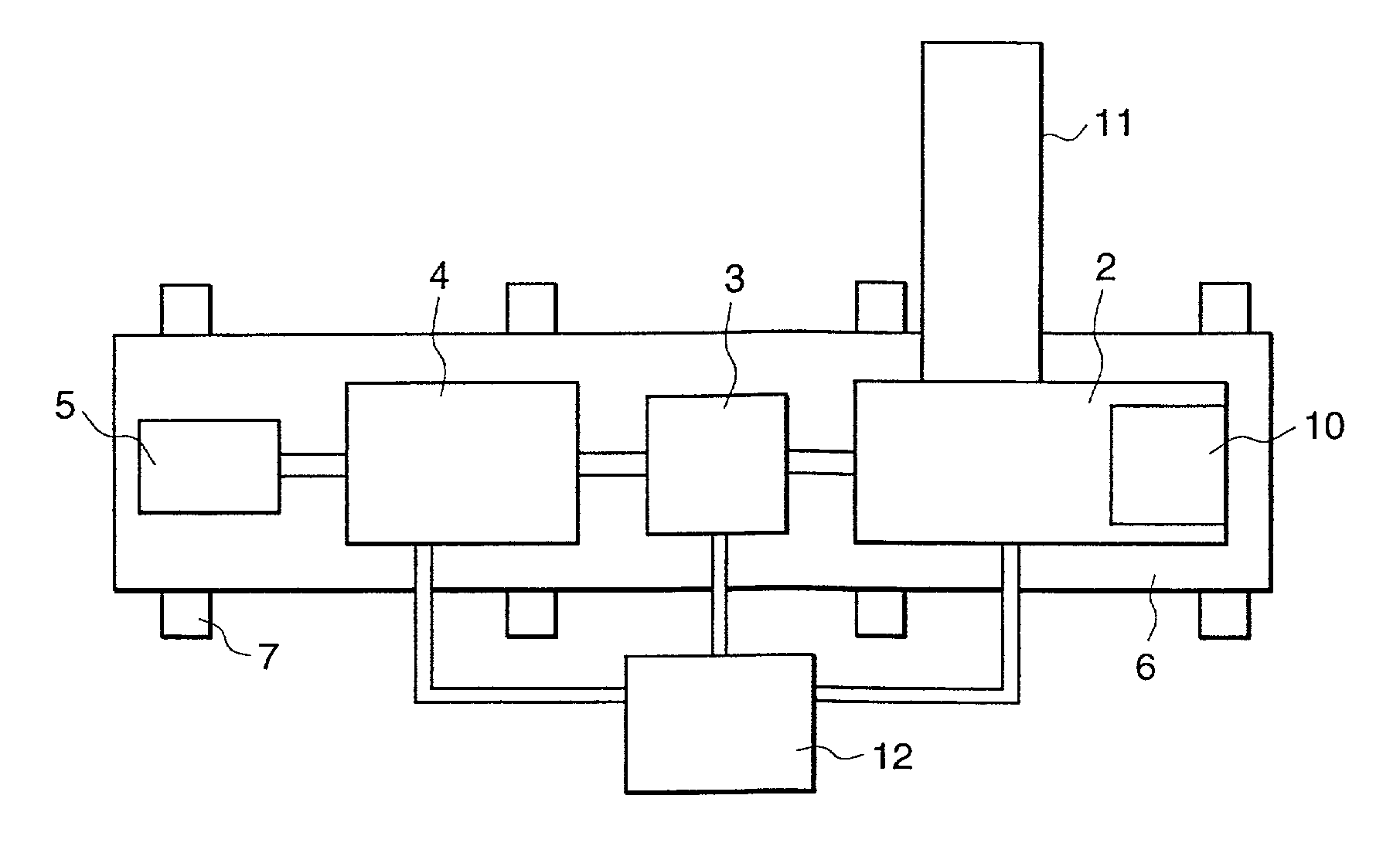
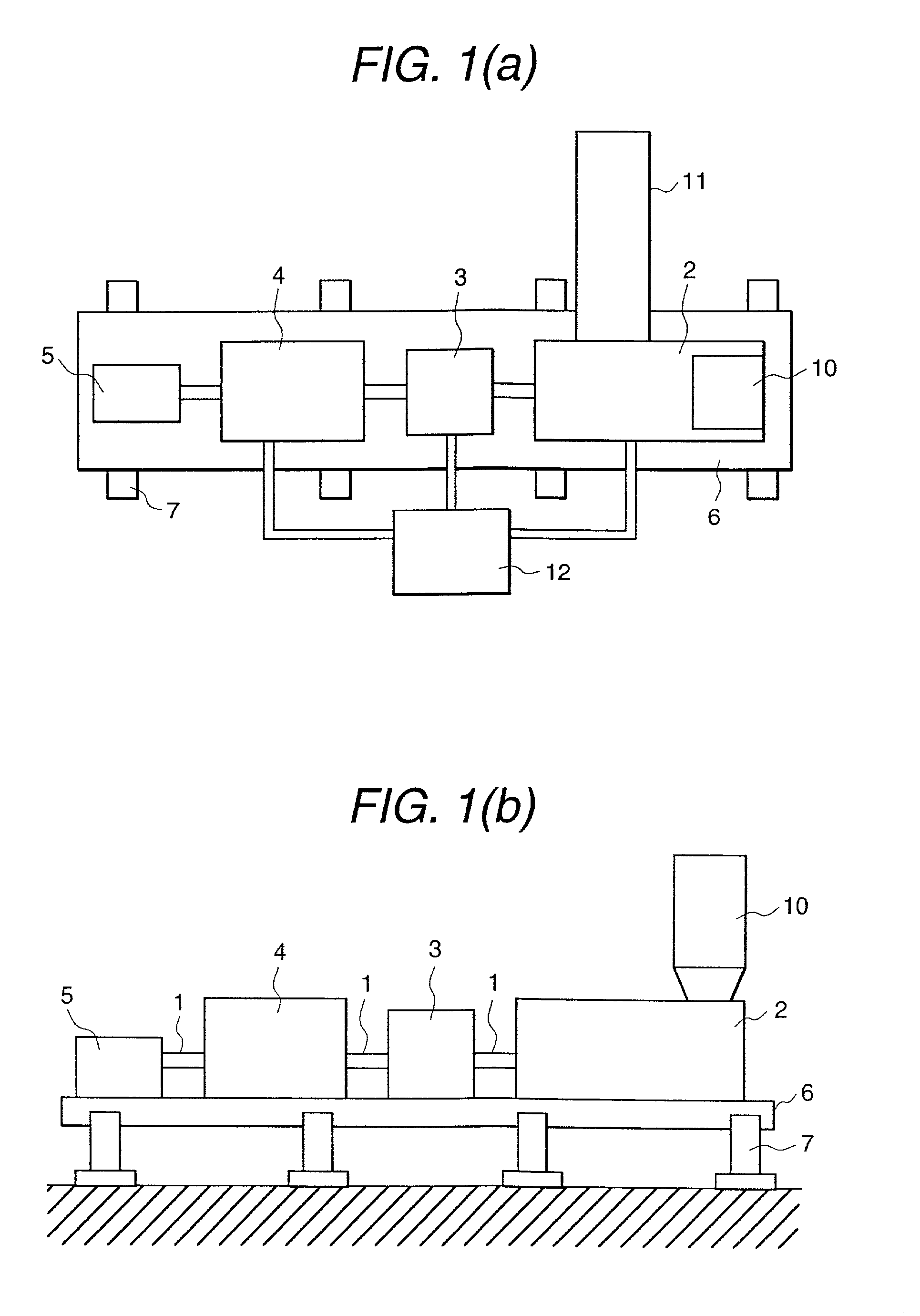
[0027] FIGS. 1(a) and 1(b) show an operational condition of a power plant which is an embodiment of the present invention. FIG. 1(a) is a plan view of the power plant, viewed from above, and FIG. 1(b) is a side view of the power plant shown in FIG. 1(a).

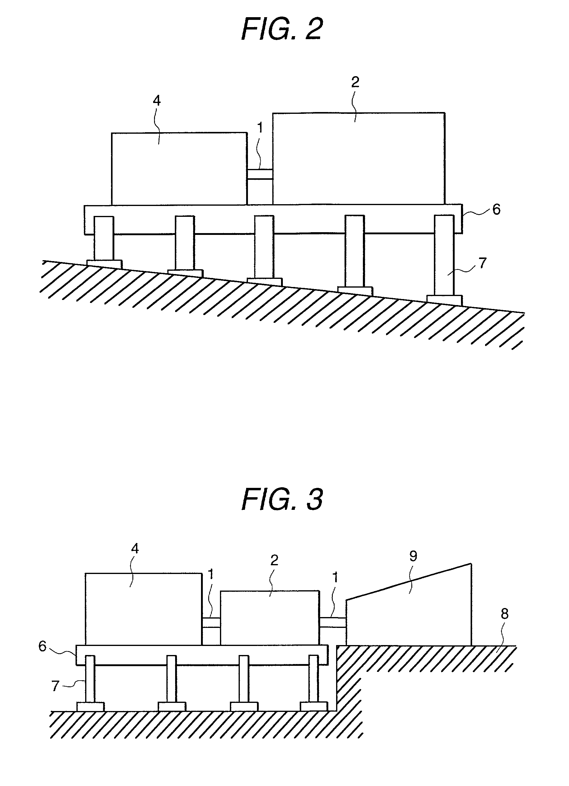
[0028] The power plant of the embodiment has a gas turbine 2, a reduction gear 3, a generator 4 and a starting apparatus 5, connected to each other by a rotating shaft 1 and each fixed on a common base 6. The gas turbine 2 is provided with a suction duct 11 connected thereto for supplying suction air to the gas turbine 2 and an exhaust duct 10 connected thereto for exhausting exhaust gas from the gas turbine 2 ...


PUM

PropertyMeasurementUnit
Lengthaaaaaaaaaa
Widthaaaaaaaaaa
Heightaaaaaaaaaa

Abstract

A turbine power plant comprises power generation apparatuses divided a plurality of modules, a common base mounting thereon the power generation apparatuses and a supporting apparatus for supporting the common base, and is characterized by a construction of the common base, constructed so as to be commonly used with a part of a transportation vehicle and a frame of the power plant.

Description

[0001] 1. Technical Field of the Invention[0002] The present invention relates to a turbine power plant, a process of installing the turbine power plant and a process of removing the turbine power plant installed at the site.[0003] 2. Description of Prior Arts[0004] Prior arts that aim to reduce a term of work for installation of a turbine power plant at the site are disclosed, for example, in JP A 11-62621, JP A 2001-173408 and JP A 11-13416.[0005] The above prior art, JP A 11-62621 discloses that auxiliary equipments such as a starting apparatus, lubrication oil apparatus, control oil apparatus and lubrication oil tank are made units, and the units are integrated with a gas turbine unit and arranged in a building.[0006] The above prior art, JP A 2001-173408 discloses that apparatuses such as a turbine, generator, and so on. and a frame made of steel are integrated and fixed into a module, and the module is transported to a building which is an installation place by a means of tran...

Claims


Application Information

Patent Timeline
IPC IPC(8): F01K13/00F01D25/28F02C7/20F16M5/00H02K5/00
CPCF01D25/285Y10T29/49229F05D2230/60F16M5/00
Inventor KUROKI, HIDETOSHITAKEHARA, ISAOWATANABE, YASUYUKITAKIHANA, SEISAKU
Owner MITSUBISHI HITACHIPOWER SYST LTD
Why Eureka
Try Eureka