
Ventilated light emitting diode matrix panel

Inactive Publication Date: 2003-04-24
ILLUMAFINITY LLC
View PDF0 Cites 14 Cited by
  • Summary
  • Abstract
  • Description
  • Claims
  • Application Information

AI Technical Summary

Problems solved by technology

Such a structure is not suitable for high intensity display, which may cause overheating.

Method used


Image

  • Ventilated light emitting diode matrix panel
  • Ventilated light emitting diode matrix panel
  • Ventilated light emitting diode matrix panel

Examples


second embodiment

[0028] FIGS. 7 and 8 show the present invention. FIG. 7 shows the top view of second metal frame 21, showing the spacers 23, LEDs 20 and the larger air ducts 272.

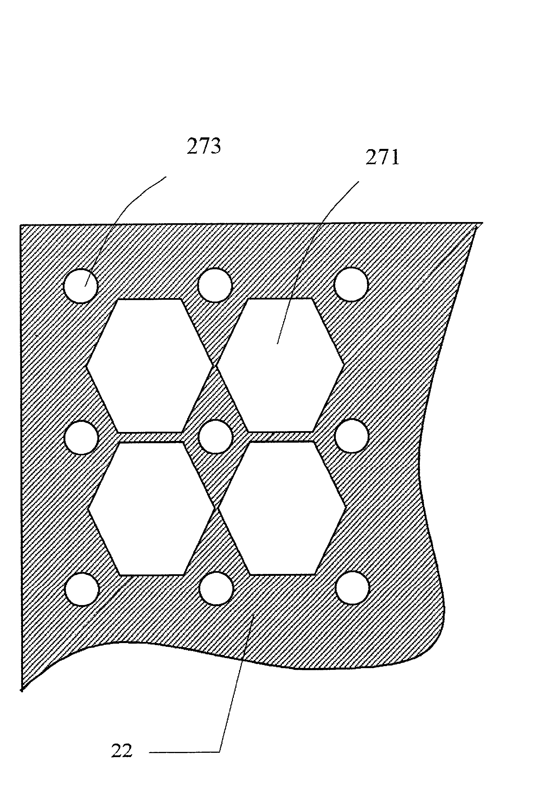
[0029] FIG. 8 shows a second metal frame 22 lying over the metal frame 21. In this structure, the first metal frame 22 has only large air ducts 271, which are offset from the large air ducts 272 of the second metal frame 21. The figure shows the top view of the first metal frame 22 stacking over the second metal frame 21, which mounts the spacers 23 and the LEDs 20 at the cross-points of the ribs of the lower metal frame 21. The air ducts 271 of the upper metal frames 22 and the air ducts 271 of the lower metal frames 21 are offset from each other to allow the top electrode of the LED 20 to be wire-bonded to the upper plate 22 by means of wire 24. The bottom electrode of the LED is in contact with the lower metal frame 21.

third embodiment

[0030] FIG. 9 shows the present invention. Two LEDs 201 and 202 are placed at each the cross-point of the lower metal frame 21. The two top electrodes of the two LEDs are both wire-bonded to the upper metal frame 22 by means of wires 24.

fourth embodiment

[0031] FIG. 10 shows the present invention. Pedestals are erected on the fist metal frame 22 so that the top electrode of each LED 20 mounted on the second metal frame 21 is planar with the top surface of the pedestal for easy wire-bonding. Spacers 23 are placed between the second metal frame and the pedestal.


PUM


Abstract

LEDs of a light matrix display are mounted between two metal frames. Each frame has air ducts to circulate air around the LEDs, thereby removing the heat generated in the LEDs and allowing higher intensity light to be emitted.

Description

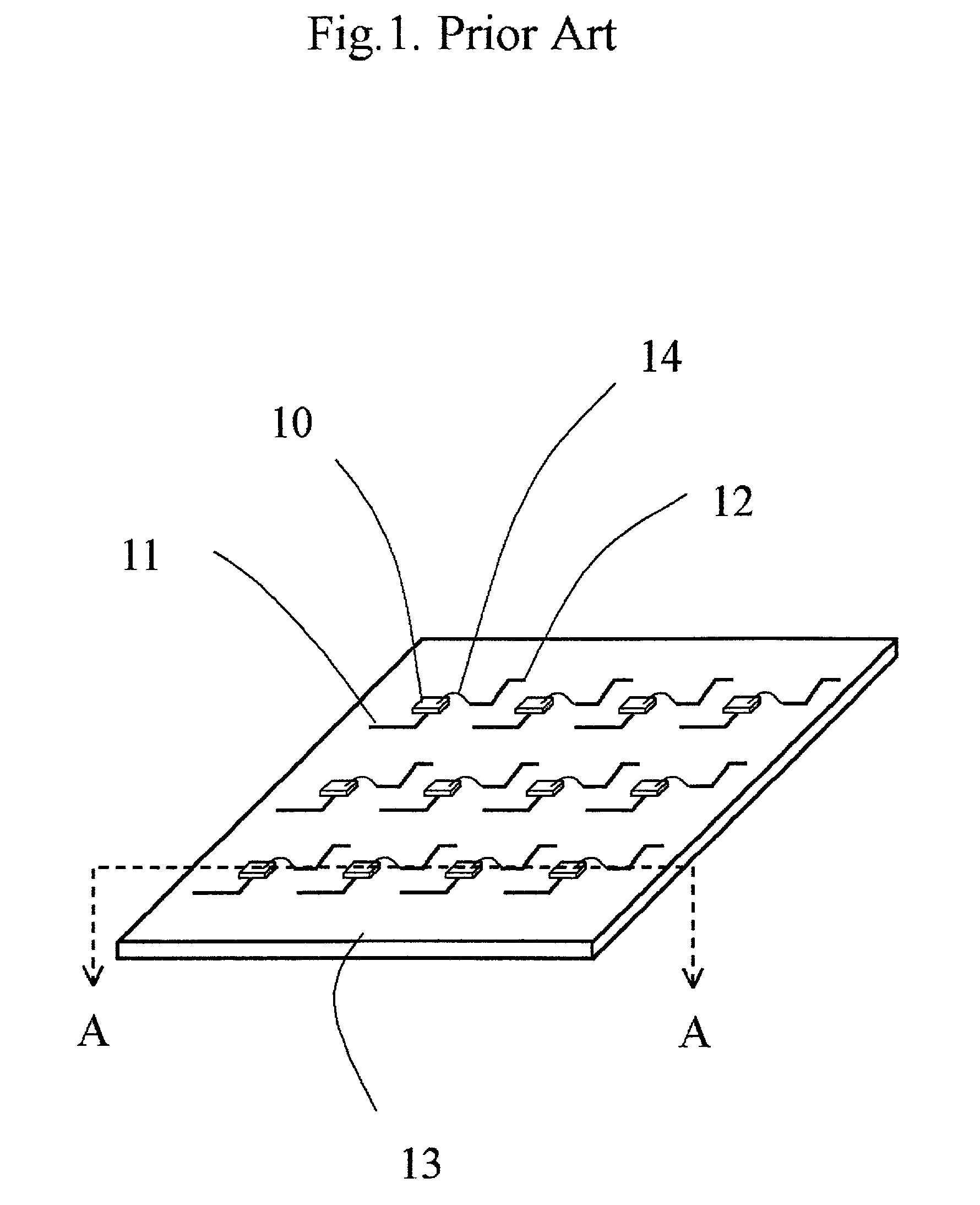
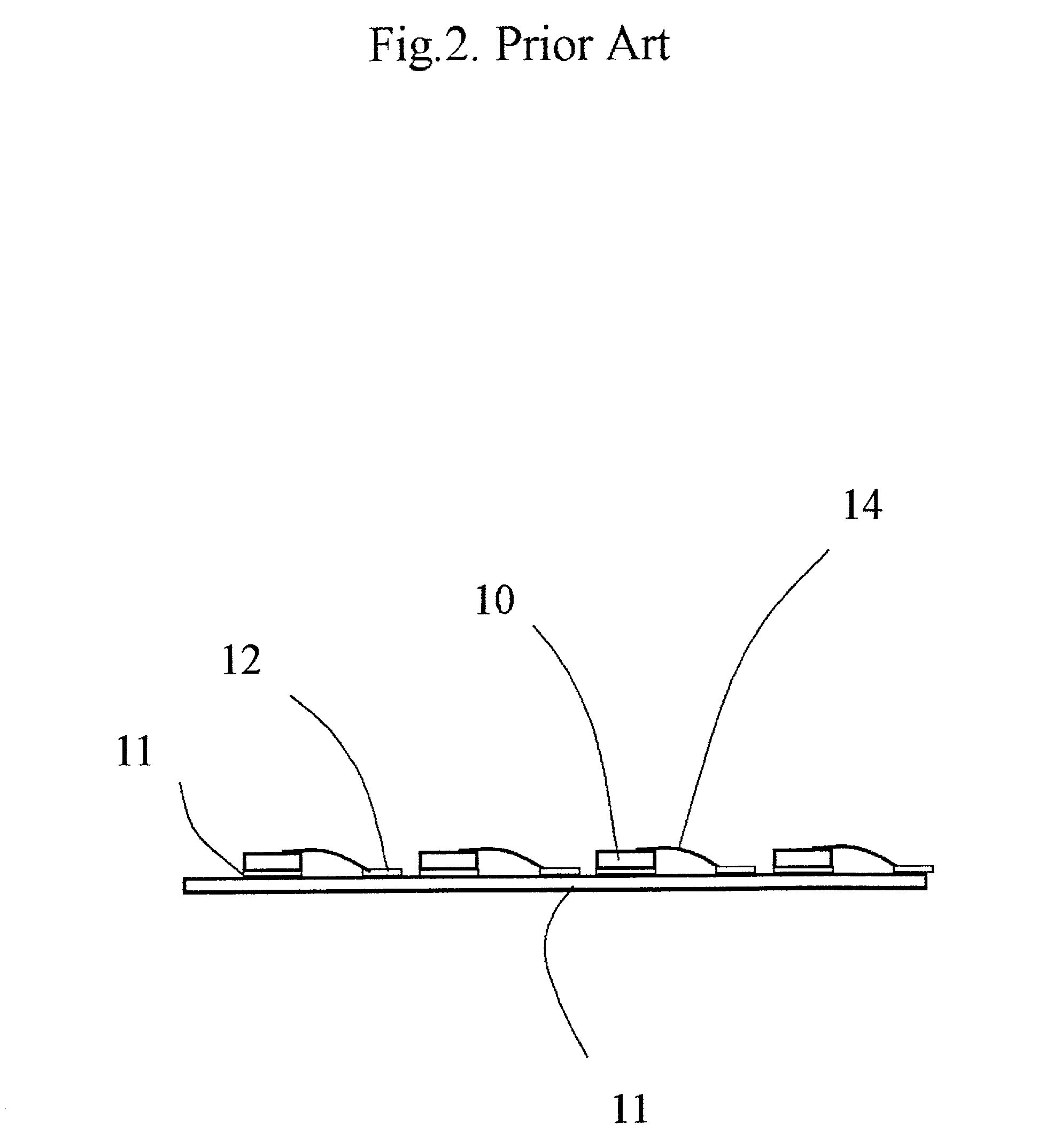
BACKGROUND OF THE INENTION[0001] (1) Field of the Invention[0002] This invention relates to light emitting diodes (LED), particularly to LED panels.[0003] (2) Brief Description of Related Art[0004] FIG. 1 shows a prior art LED matrix panel. Each LED is mounted on an insulating substrate 13 with bottom electrode bonded by connection 11 and the top electrode wire-bonded to connection 12 as shown in the side view FIG. 2. The shortcoming of this kind of matrix panel is that there is no provision for heat removal. Such a structure is not suitable for high intensity display, which may cause overheating.[0005] An object of this invention is to provide ventilation for the LED matrix to prevent overheating. Another object of this invention is provide multi-color LED matrix display.[0006] These objects are achieved by provide air ventilation through each LED. There are two metal frames spaced from each other. Each LED is mounted on one of the two metal frames. Each metal frame has air ducts, ...

Claims


Application Information

Patent Timeline
Patent Type & Authority Applications(United States)
IPC IPC(8): G09F9/33H01L25/075H01L33/62H01L33/64
CPCG09F9/33H01L25/0753H01L33/62H01L33/648H01L2224/73265H01L2224/48091H01L2924/00014H01L2924/00
Inventor WU, JIAHN-CHANG
Owner ILLUMAFINITY LLC
Learn More