
Optical disk label and method

Inactive Publication Date: 2003-04-24
CONCEPT DESIGN ELECTRONICS & MFG
View PDF15 Cites 6 Cited by
  • Summary
  • Abstract
  • Description
  • Claims
  • Application Information

AI Technical Summary

Benefits of technology

[0008] It is another object of the invention to provide a label for an optical disk which permits text and / or graphics to be placed over the hole in the center of the optical disk without interfering with the utility of the hole.
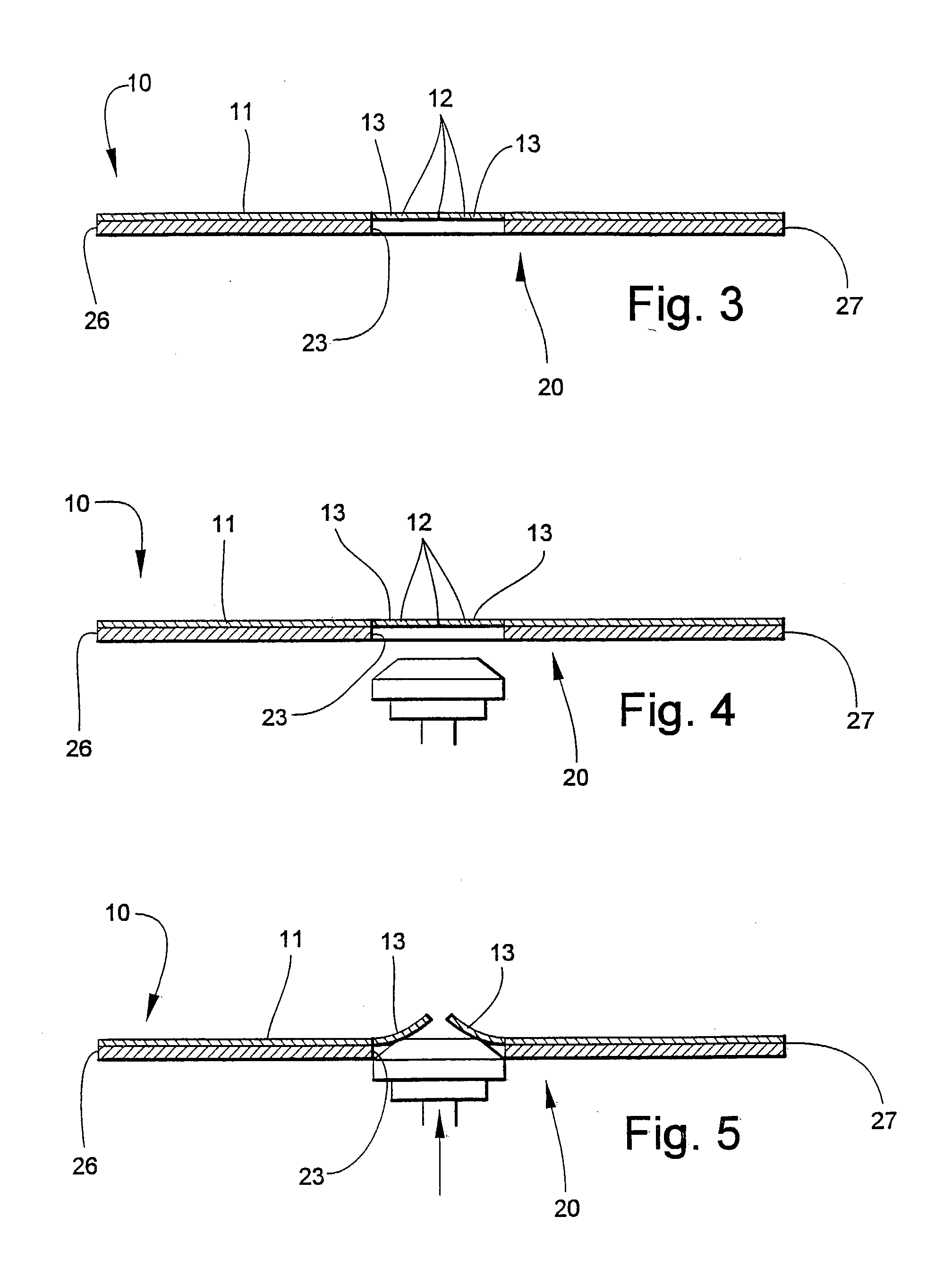
[0019] According to yet another preferred embodiment of the invention, an optical disk of the type having a hole therethrough for being positioned onto a rotatable spindle by which the optical disk is rotated is provided. This optical disk includes the combination therewith of a label formed of a sheet having a size and shape for being positioned on and adhered to the optical disk and overlying the hole, the sheet having sufficient thinness and flexibility to be deflected upwardly from the hole to permit the spindle to fit into the hole to a degree sufficient to rotate the disk.
[0059] Referring now to FIG. 9, an optical disk 55 is shown in cross-section, and includes a hole 56 covered by an integrally-molded, very thin web 57 which serves as a substrate which can be silk-screened or otherwise provided with text or graphics material, or merely painted with a desired color. The web 57 is provided with slits 58 arranged in a pattern such as shown above. The slits 58 permit the adjacent segments 59 to be deflected upwardly by an object such as a spindle inserted through the hole 56, as described above. The thickness and thus the flexibility is determined empirically based upon the plastic material from which the optical disk is molded.
[0062] FIGS. 14 and 15 illustrate a further embodiment 90 wherein a disk body 91 has a hole 92 covered by an integrally-molded, very thin web 94 that serves as a substrate which can be silk-screened or otherwise provided with a label 96 with text and / or graphics material 97, or merely painted with a desired color. As distinct from the disk 55 shown in FIG. 9, the web 94 is solid. According to one embodiment of the invention the web 94 is sufficiently thin that it can easily be broken away from the surrounding annular edge of the disk body 91 by which it is integrally-formed with the disk body. See FIGS. 16 and 17. This is suitable in a situation where, for example, the disk distributor or advertiser is principally interested in the initial appearance of the disk 90 before purchase, and is not concerned with whether some of the label 96 is later removed by breaking out the web 94 and discarding it when the disk 90 is first used. An even thinner annular weakness line (not shown) may be formed at the point of juncture between the web 94 and the disk body 91 to further facilitate separation of the web 94 from the disk body 91 and to provide a clean, smooth break line. While the thickness of the web 94 will vary based on materials used, in general the web 94 should be about {fraction (1 / 10)}th the thickness of the disk 90.
[0065] As is shown in FIG. 23, a label 110 is comprised of a thin patch 111 of film material with an adhesive on a back side and suitable for being printed on the front side. As is shown in FIG. 24, the label 110 is positioned on a disk 115 over a hole 116 formed in a disk body 117. The label 110 sized to be approximately 5-20 percent larger in diameter than the hole 116 to be covered, so that the peripheral area of the label 110 overlies the hole 116 and is adhered to the disk body 117 in the marginal area adjacent the hole 106. The label 110 can be printed on by silk-screening or otherwise, so that desired text or graphical material can be applied over the entire top surface of the disk 115. If desired, the label 110 can be removed by raising a corner sufficiently to grasp it between two fingers, and then pulling it to detach it from the disk body 117. The label 110 can be made sufficiently thin and resilient that the spindle will deflect the label 110 upwardly without tearing or detaching it from the disk 117. In this way any text or graphics material printed or otherwise applied to the label 110 remains intact.

Problems solved by technology

The existence and necessity of the hole presents a significant disadvantage in the use of optical disks as advertising and promotional products, since the hole is relatively large in relation to the overall size of the disk, particularly in the smaller format disks and those with irregular shapes.

Method used


Image

  • Optical disk label and method
  • Optical disk label and method
  • Optical disk label and method

Examples


Embodiment Construction

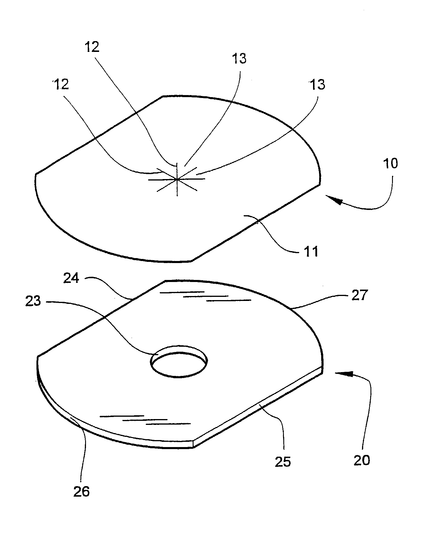
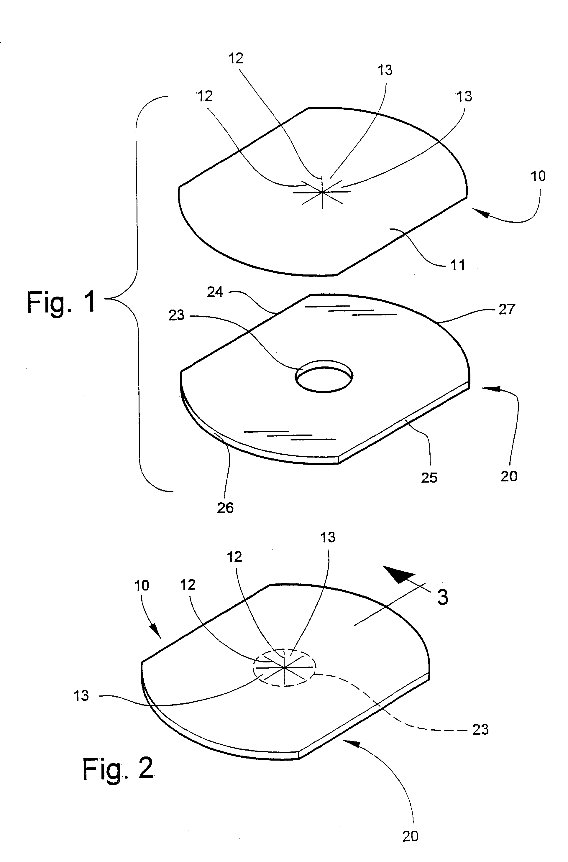
[0056] Referring now specifically to the drawings, a label according to the present invention is illustrated in FIG. 1 and shown generally at reference numeral 10. Label 10 is any suitable sheet material 11, such as paper or card stock, metal or plastic foil, or other plastic sheet material. Label 10 can be shaped to fit onto any optical disk of any size or shape. A plurality of slits 12 are formed in the sheet 11 and converge and intersect to form a star-shaped area defined by adjacent sheet segments 13. The slits 12 are placed in the label 10 in registration with the hole 23 so that when the label 10 is applied to the optical disk 20, the sheet segments 13 overlie the hole 23. The slits may be cut by any suitable method. As is shown in FIG. 2, the label 10 completely covers the hole 23 and renders it invisible. The slits 12 are only faintly visible, and lie in the plane of the sheet 11. This permits text and or graphics material to be placed on the label 10 without regard to the e...


PUM

PropertyMeasurementUnit
Sizeaaaaaaaaaa
Flexibilityaaaaaaaaaa
Adhesivityaaaaaaaaaa

Abstract

An optical disk of the type rotated by a spindle positioned in a centrally-located hole, and including a disk body including an annular data area, and a centrally-located, integrally-formed annular web positioned radially inward from the annular data area and covering a hole formed in the disk body. The annular web is formed sufficiently thin to be deflected upwardly out of the plane of the disk body by the spindle during placement on the spindle and during rotation. The web may be broken away from the disk, or made sufficiently thin and resilient that it will deform upwardly when placed on the spindle and resume its former position when removed.

Description

TECHNICAL FIELD AND BACKGROUND OF THE INVENTION[0001] This invention relates to a label for an optical disk. Optical disks presently take many forms, and include plastic disks which contain digital data which may represent computer software, music, video, graphics and many other types of digital data. Such disks are presently made in many sizes and are referred to by different names, for example, CD's, compact disks, optical disks, DVD's, and include unrecorded disks which can be "burned" by consumers and disks which are capable of being recorded and then re-recorded. These disks are typically circular.[0002] Optical disks are also now made and sold which have irregular shapes, and are used for many purposes including business advertising. Such disks can be formed in virtually any shape so long as they will fit into and function in a disk player. One such shape commonly made and distributed is a "business card" disk, which comprises an optical disk which has been cut down in size so...

Claims


Application Information

Patent Timeline
IPC IPC(8): G09F3/02G09F3/10G11B23/40
CPCG09F3/02G09F3/10G11B23/40Y10T428/21Y10T428/24479Y10T428/24314Y10T428/218Y10T428/24331
Inventor CLARK, RICHARD LEE
Owner CONCEPT DESIGN ELECTRONICS & MFG
Learn More