Fire extinguishing installation with valve comprising a spindle

a technology of fire extinguishing and valve, which is applied in fire rescue and other directions, can solve the problems of increasing the volume of liquid in the extinguishing medium and the droplet size of the extinguishing medium, and achieves the effects of efficient extinguishing of fire, large drop, and low kinetic energy

Inactive Publication Date: 2003-05-01
MARIOFF CORP OY
View PDF0 Cites 5 Cited by
  • Summary
  • Abstract
  • Description
  • Claims
  • Application Information

AI Technical Summary

Benefits of technology

0014] The most important advantage of the fire extinguishing installation of the invention is that it is able to first supply extinguishing medium that has a low kinetic energy and very little liquid, which, when expanding in a hot environment, is unable to cause a harmful pressure impact or pressure wave, after which the installation is able to supply extinguishing medium having relatively large drops and relatively much liquid and kinetic energy, said latter extinguishing medium causing further cooling of the fire site. Due to said two-step operation, the extinguishing medium does n...

Problems solved by technology

The two-step operation of the extinguishing installation is typically such that the installation first supplies a large amount of very small droplets...

Method used


Image

  • Fire extinguishing installation with valve comprising a spindle
  • Fire extinguishing installation with valve comprising a spindle

Examples


Embodiment Construction

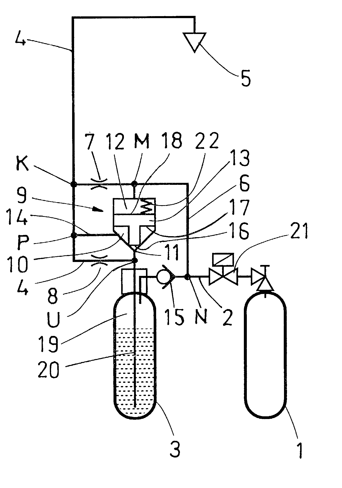
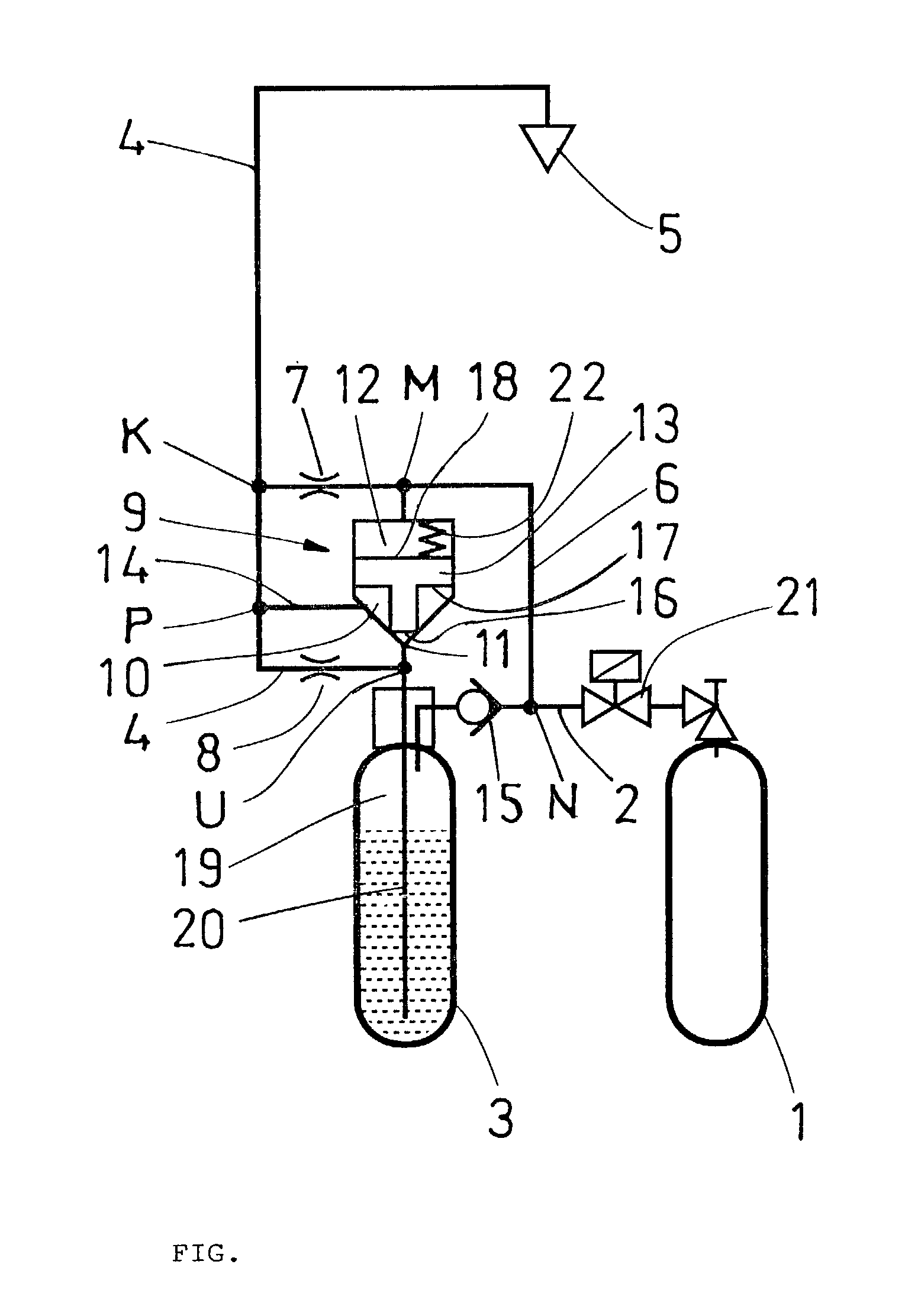
[0016] The drawing shows a simplified version of a fire extinguishing installation and its main components. The installation comprises a gas container 1, which is connected by means of a pipe 2 or other line, such as a hose, to a liquid container 3. The gas container contains nitrogen, other incombustible gas or air. The pressure in the container 1 is between 50 and 300 bar, e.g. about 200 bar. The liquid container 3 contains a hydrous substance, preferably water, which may have small additions of some substance preferably used in fire extinguishing, such as an anti-freeze agent. The gas discharged from the gas container 1 is arranged to propel liquid from the liquid container 3 via the pipe 2 via an ascending pipe 20 and an outlet U, and via a throttle 8 to a feed pipe 4 (outlet pipe) and from there further to a spray head 5.

[0017] A pipe 6 originates from point M in the pipe 2 between the gas container 1 and the liquid container 3 to the feed pipe 4. At connection point K, the pip...


PUM


Abstract

A fire extinguishing installation comprising a liquid container (3), a gas container (1), and a feed line (4) to at least one spray head (5), the gas container being connected at a connection point (K) via a second line (6) to the feed line, and a valve (9) connected to the outlet (U) of the liquid container and to the feed line. In order for the fire extinguishing installation to be suitable particularly for extinguishing liquid fires without it causing splashing of the burning liquid, the valve (9) comprises a liquid space (10), connected to the feed line (4), a gas space (12), connected to the second line (6), and a spindle (13) arranged between the liquid space (10) and the gas space (12), which spindle either prevents or enables communication between an outlet (U) of the liquid container (3) and the liquid space (10).

Description

BACKGROUND OF THE INVENTION[0001] The invention relates to a fire extinguishing installation comprising a liquid container connected to a gas container by means of a first line for discharging liquid from the liquid container via an outlet of the liquid container and a feed line to at least one spray head, the gas container being connected at a connection point via a second line to the feed line, and a valve one opening of which is connected to the outlet of the liquid container and another opening of which is connected to the feed line. The gas container and the liquid container form a hydraulic accumulator. The fire extinguishing installation of the invention is intended for local or `target` extinguishing and it is very well suited to extinguish liquid fires.[0002] JP 11192320 discloses a fire extinguishing installation of the above type. The installation mixes gas and water at a predetermined ratio into a supply pipe. WO 95 / 28204 discloses a fire fighting installation enabling t...

Claims


Application Information

Patent Timeline
IPC IPC(8): A62C3/06A62C35/02A62C35/68
CPCA62C35/023A62C35/68
Inventor SUNDHOLM, GORAN
Owner MARIOFF CORP OY
Why Eureka
Try Eureka