
Blower with directional output nozzle

a directional output and blower technology, applied in the field of blowers, can solve the problems of reducing the efficiency of the blower, confusion of the operator, loss of productivity, etc., and achieve the effect of optimizing air flow and maximizing performan

Inactive Publication Date: 2003-05-01
EAVENSON JIMMY N SR +2
View PDF5 Cites 19 Cited by
  • Summary
  • Abstract
  • Description
  • Claims
  • Application Information

AI Technical Summary

Benefits of technology

[0011] An improved blower with a directional output nozzle is provided for various tasks such as moving debris or drying surfaces. The blower includes a frame mounted on wheels and a motor mounted to the frame. The blower also includes a housing with an inlet opening and directional output nozzle. An impeller is located in the blower housing and is driven by the motor to generate airflow. As the impeller rotates, air is drawn in through the inlet opening and is discharged through the output nozzle. The output nozzle can be repositioned by rotation by either local control or remote actuation. The nozzle can also be arranged in various configurations such as diameter, length, shape, etc. to optimize air flow with respect to air volume, air velocity and head pressure to maximize performance for specific tasks such as leaf blowing, sidewalk clearing / cleaning, drying grass or pavement and inflating inflatable devices.

Problems solved by technology

The designs also require that the user adjust the control means that has almost infinite settings and this can provide operator confusion, loss of productivity, and reduced blower efficiency.

Method used


Image

  • Blower with directional output nozzle
  • Blower with directional output nozzle
  • Blower with directional output nozzle

Examples


Embodiment Construction

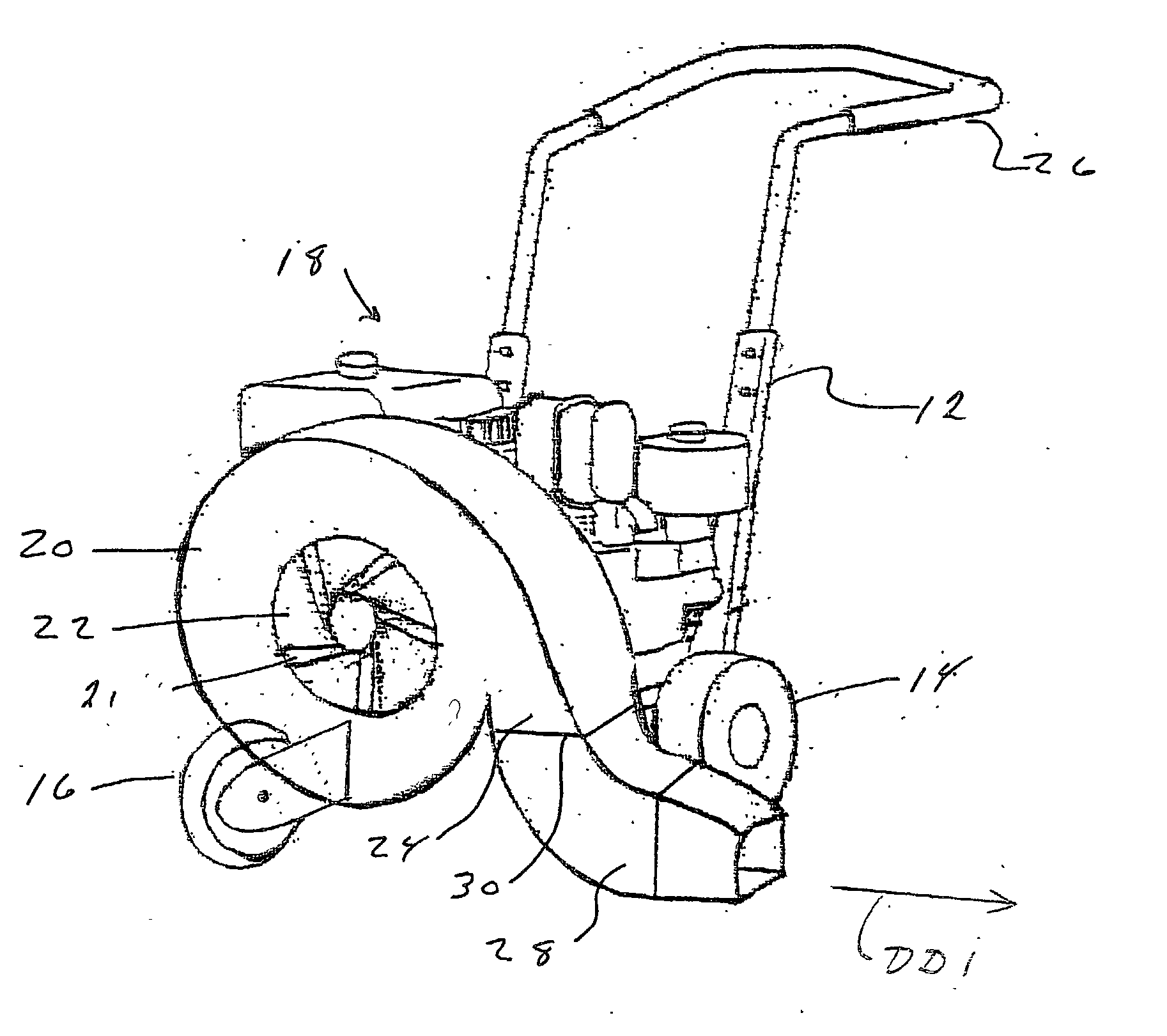
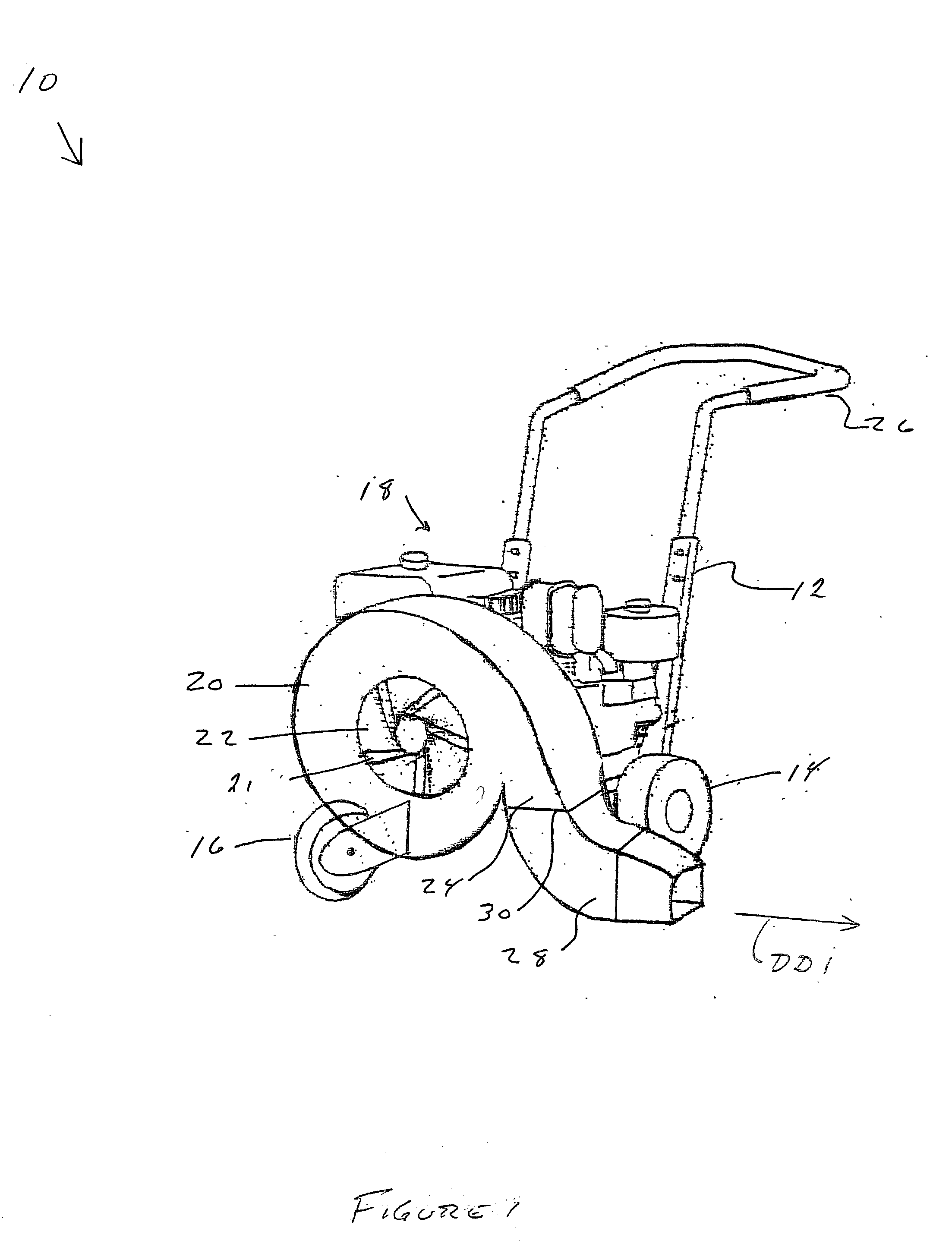
[0018] Referring now to the drawings wherein the showings are for purposes of illustrating a preferred embodiment of the invention only and not for purposes of limiting the same, FIG. 1 is directed to a centrifugal-type blower 10 having a frame 12 mounted on wheels 14 and 16. A motor 18 is mounted to frame 12. A blower housing 20 that houses an impeller 21 is mounted to frame 12. A handle 26 is also attached to the frame 12 and is adapted for an operator to push in order to move the blower 10 along a surface to be cleared, dried, etc.

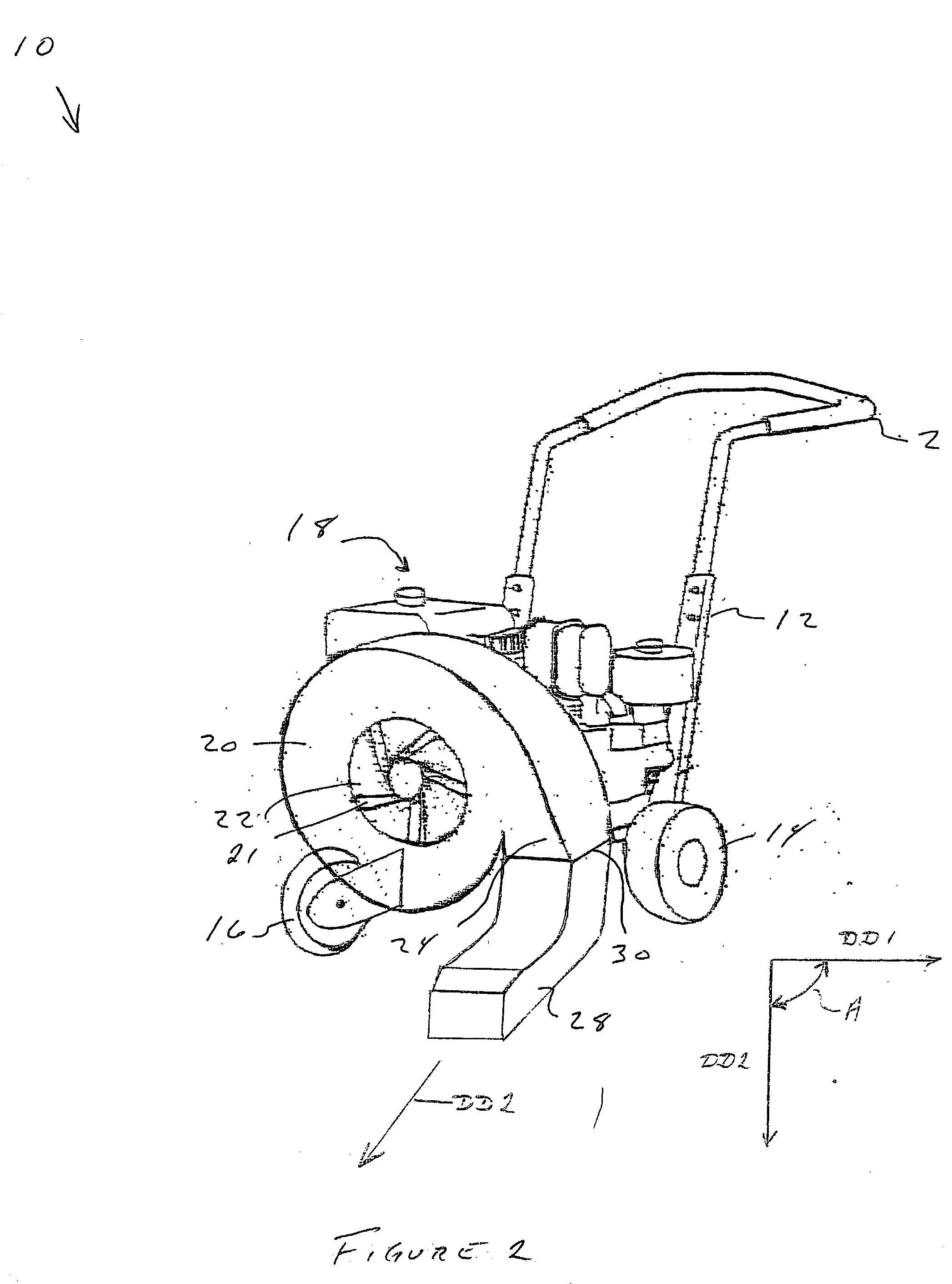
[0019] With reference to FIGS. 1 and 2, the blower housing 20 further consists of an air inlet 22, an outlet 24, and a nozzle 28. The nozzle 30 is connected to the outlet 24 in such a manner that allows the nozzle 28 to rotate about a horizontal axis 30 and between a first and second position with respect to the blower housing 20. It should be noted that the nozzle 28 can be connected to the outlet 24 by any mechanical means necessary chosen with sound ...


PUM


Abstract

An improved blower with a directional output nozzle is provided for various tasks such as moving debris or drying surfaces. The blower includes a frame mounted on wheels and a motor mounted to the frame. The blower also includes a housing with an inlet opening and directional output nozzle. An impeller is located in the blower housing and is driven by the motor to generate airflow. As the impeller rotates, air is drawn in through the inlet opening and is discharged through the output nozzle. The output nozzle can be repositioned by rotation by either local control or remote actuation.

Description

[0001] This application claims priority to U.S. Ser. No. 60 / 325,892 entitled BLOWER WITH DIRECTIONAL OUTPUT NOZZLE, filed Sep. 28, 2001. This invention pertains to applications for moving debris and more specifically to a directional output nozzle to be mounted on a blower housing of a blower that allows rotation of the nozzle.I. BACKGROUND OF THE INVENTION[0002] A. Field of Invention[0003] This invention pertains to a blower for moving debris or drying surfaces, and more specifically, to a directional output nozzle to be mounted on a blower housing of a blower that allows for rotation of the discharge chute in order to vary the direction of the airflow.[0004] B. Description of Related Art[0005] Mobile blowers for moving leaves and other debris from lawns, driveways or other surfaces are known in the art. Generally, a blast of air is directed from a blower outlet toward or across the surface to be cleared. The blower outlet is usually adapted to be adjacent the ground so that the ai...

Claims


Application Information

Patent Timeline
IPC IPC(8): B65G53/04B65G53/42
CPCA01G1/125A01G20/47
Inventor EAVENSON, JIMMY N. SR.KOCKA, WILLIAMSAHA, AMIT
Owner EAVENSON JIMMY N SR
Learn More