
Apparatus dispensing rechargeable refrigerating elements

Inactive Publication Date: 2003-05-15
TECHNI LOISIRS
View PDF1 Cites 3 Cited by
  • Summary
  • Abstract
  • Description
  • Claims
  • Application Information

AI Technical Summary

Benefits of technology

[0036] In FIG. 2 it is very clear that input orifice 4 and output orifice 7 of the refrigeration and storage module 6 are located in essentially the same plane and at the upper portion. They traverse upper wall 61 of insulated case 60 along generally vertical axes. This particular arrangement of input orifice 4 and output orifice 7 at the upper part of insulated case 60, combined with the cubic shape of the case, advantageously prevents cold from leaking and consequently is conducive to increasing refrigeration temperature to as low as -35.degree. C.
[0050] To recycle refrigerating elements 10 when the frigories have been discharged, the user introduces them into input orifice 3 after having positioned them correctly. Refrigerating elements 10 descend one by one, by gravity, along inclined ramp 50 to output opening 4. Simultaneously, presence detector 30, located at the back of input orifice 3, automatically sends signals to the cylinder of runner 95 to effect the exchange of refrigerating elements 10, as well as to motor 55 which controls the cleaning and disinfection mechanism, that is, brushes 53 and the simultaneously sprayed liquid disinfectant. Thus, refrigerating elements 10 are cleaned and disinfected before being introduced into refrigeration and storage module 6 through input orifice 4. This prevents any contamination of the refrigeration zone. Input and disinfection module 2 is completely separated and isolated from refrigeration and storage module 6. Thus, the electric and electronic equipment provided in this module can be standard equipment.
[0052] From this description it is apparent that the invention achieves all its objectives and in particular, that the specific design of the two modules 2 and 6, as well as the positioning of input and output orifices 4 and 7 at the upper part of insulated case 60, increases refrigeration power considerably.

Problems solved by technology

The dispensing apparatus known in the art does not achieve this objective, primarily because of cold escaping at the outlet orifice located on the lower portion of the dispenser.

Method used


Image

  • Apparatus dispensing rechargeable refrigerating elements
  • Apparatus dispensing rechargeable refrigerating elements
  • Apparatus dispensing rechargeable refrigerating elements

Examples


Embodiment Construction

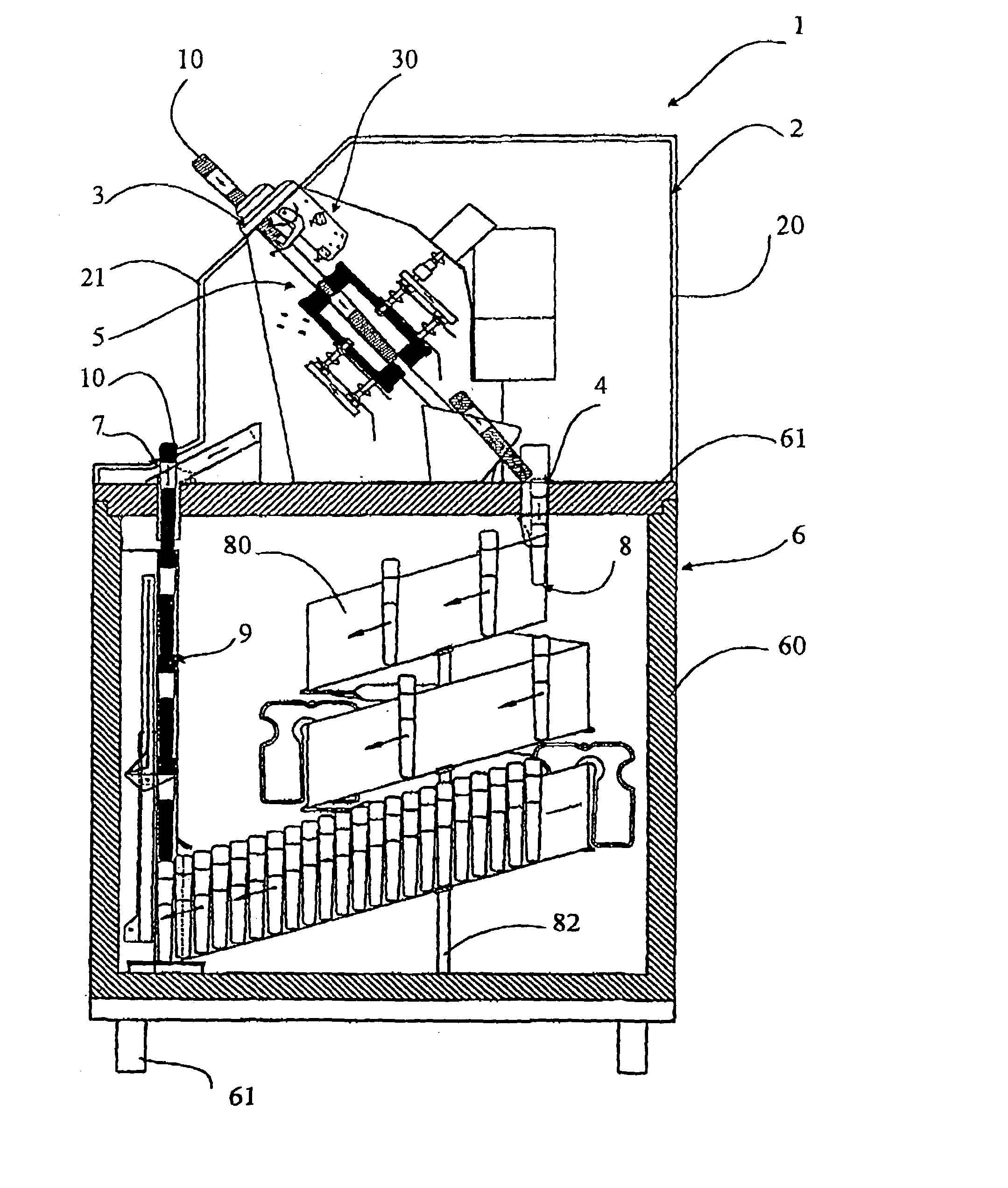
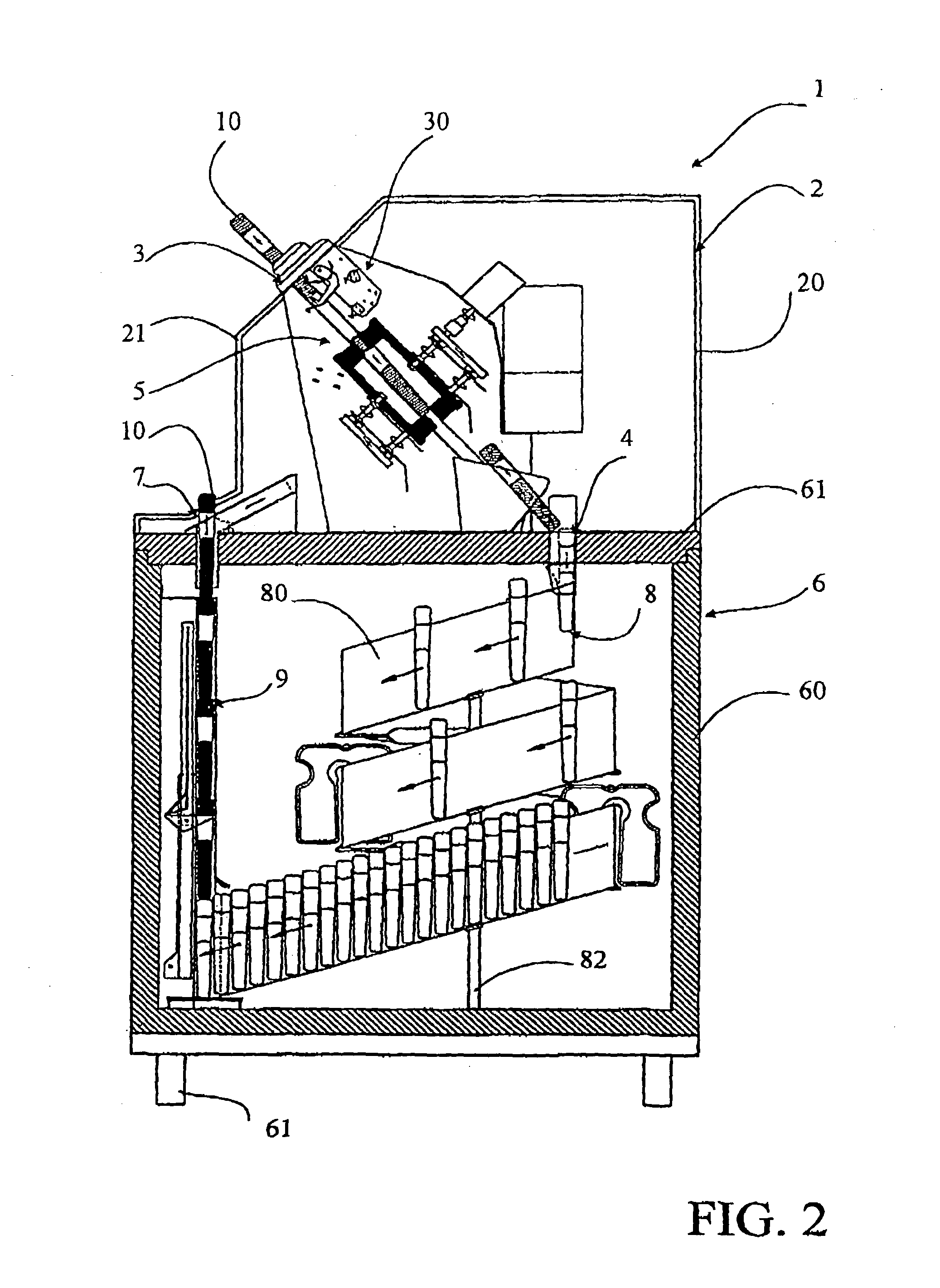
[0008] The present invention proposes overcoming this disadvantage with a dispenser for high capacity refrigerating elements which dispenses and recycles refrigerating elements that can be placed in containers for transporting frozen products and which maintains the cold chain from the dispenser to the consumer's home.

[0009] To achieve this, the invention concerns an apparatus for dispensing refrigerating elements such as that described in the preamble, characterized:

[0010] in that the inlet and disinfection module is located above said refrigeration and storage module,

[0011] in that the input and output orifices of said refrigeration and storage module are located in the upper portion of said module,

[0012] and in that the refrigeration and storage module comprises a third transfer means for lifting the refrigerating elements to the input orifice.

[0013] Preferably the input and output orifices of the refrigeration and storage module are located in essentially the same plane.

[0014] I...


PUM


Abstract

The invention concerns a dispensing apparatus (1) with high refrigerating power, for delivering to users refrigerating elements (10) capable of diffusing frigories over a relatively great lapse of time so as to avoid interrupting the cold chain, comprising an input and disinfecting module (2) arranged above the refrigerating and storage module (6). The input (4) and output (7) orifices of the refrigerating and storage module are located substantially in the same plane and in the upper part of the docule which further includes third transfer mechanism (9) designed to lift the refrigerating elements towards the output orifice.

Description

TECHNICAL DOMAIN[0001] The present invention concerns an apparatus for dispensing rechargeable refrigerating elements, especially plates or packets containing a substance formulated to accumulate frigories, comprising at least:[0002] an input and disinfection module for said refrigerating elements provided with an input opening, an output opening, and a first means for transferring said elements between the two orifices; and[0003] a refrigeration and storage module for said refrigerating elements provided with an insulated case, a cold generating device for charging said refrigerating elements with frigories, an input orifice corresponding to the output orifice of said input and disinfection module, and an output orifice, said orifices traversing a wall of said insulated case; and with a second transfer means using gravity to transport said refrigeration elements for recycling inside said refrigeration and storage module.PRIOR ART[0004] It is well known that a regard for maintaining...

Claims


Application Information

Patent Timeline
IPC IPC(8): B65G11/20B65G11/02B65G57/30B65G60/00F25D3/00F25D13/06G07F7/06G07F9/10G07F11/16G07F11/32
CPCG07F7/06G07F17/0071G07F11/32G07F11/16G07F9/105G07F11/163
Inventor FRANCI, FRANCOIS-MARIE
Owner TECHNI LOISIRS
Features
  • Generate Ideas
  • Intellectual Property
  • Life Sciences
  • Materials
  • Tech Scout
  • Unparalleled Data Quality
  • Higher Quality Content
  • 60% Fewer Hallucinations
Learn More