Non aqueous electrolyte secondary battery

Inactive Publication Date: 2003-05-22
SANYO ELECTRIC CO LTD
View PDF10 Cites 24 Cited by
  • Summary
  • Abstract
  • Description
  • Claims
  • Application Information

AI Technical Summary

Benefits of technology

0005] An object of the present invention is to solve the above-described problems of a non aqueous electrolyte secondary battery. It is an object to provide a non aqueous electrolyte s

Problems solved by technology

However, in such non aqueous electrolyte secondary battery in which charging and discharging takes place by movement of lithium ions between the positive and negative electrodes, the organic solvent of the non aqueo

Method used


Image

  • Non aqueous electrolyte secondary battery
  • Non aqueous electrolyte secondary battery
  • Non aqueous electrolyte secondary battery

Examples


example 1

[0031] In this example, a non aqueous electrolyte in which LiN(CF.sub.3SO.sub.2).sub.2 as a lithium salt was added in an amount of 1 mol / l to trimethyloctyl ammonium.trifluoromethanesulfonimide ((CH.sub.3).sub.3N.sup.+(C.sub.8H.sub.17) N.sup.-(CF.sub.3SO.sub.2).sub.2-) as a room temperature molten salt was used.

[0032] A natural graphite having an average particle diameter of 18 .mu.m, a true density of 2.20 g / cm.sup.3, a specific surface area of 6.3 m.sup.2 / g, d.sub.002 of 3.35 .ANG. and Lc (size in a direction of the c-axis) of 100 nm was used as a material for a positive electrode that is capable of occluding and discharging anions. Polyfluorovinylidene dissolved in N-methyl-2-pyrrolidone as a binding agent was added to the natural graphite in a ratio of the graphite to polyfluorovinylidene of 85:15 by weight. They were mixed to make a slurry in a mortar. The slurry was coated on an aluminum film, and dried at 110.degree. C. to prepare a positive electrode of 2 cm.times.2 cm.

[0033...

example 2

[0036] In this example, a non aqueous electrolyte in which LiN(CF.sub.3SO.sub.2).sub.2 as a lithium salt was added in an amount of 1 mol / l to trimethyloctyl ammonium.trifluoromethanesulfonimide ((CH.sub.3).sub.3N.sup.+(C.sub.8H.sub.17) N.sup.-(CF.sub.3SO.sub.2).sub.2-) as a room temperature molten salt was also used.

[0037] To prepare a negative electrode the same natural graphite as used in Example 1 was used as a material that is capable of occluding and discharging cations. Polyfluorovinylidene dissolved in N-methyl-2-pyrrolidone as a binding agent was added to the natural graphite in a ratio of the graphite to polyfluorovinylidene of 85:15 by weight. They were mixed to make a slurry in a mortar. The slurry was coated on a copper film, and dried at 110.degree. C. to prepare a negative electrode of 2 cm.times.2 cm.

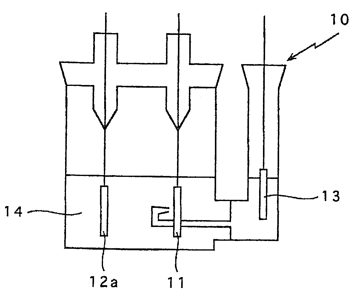
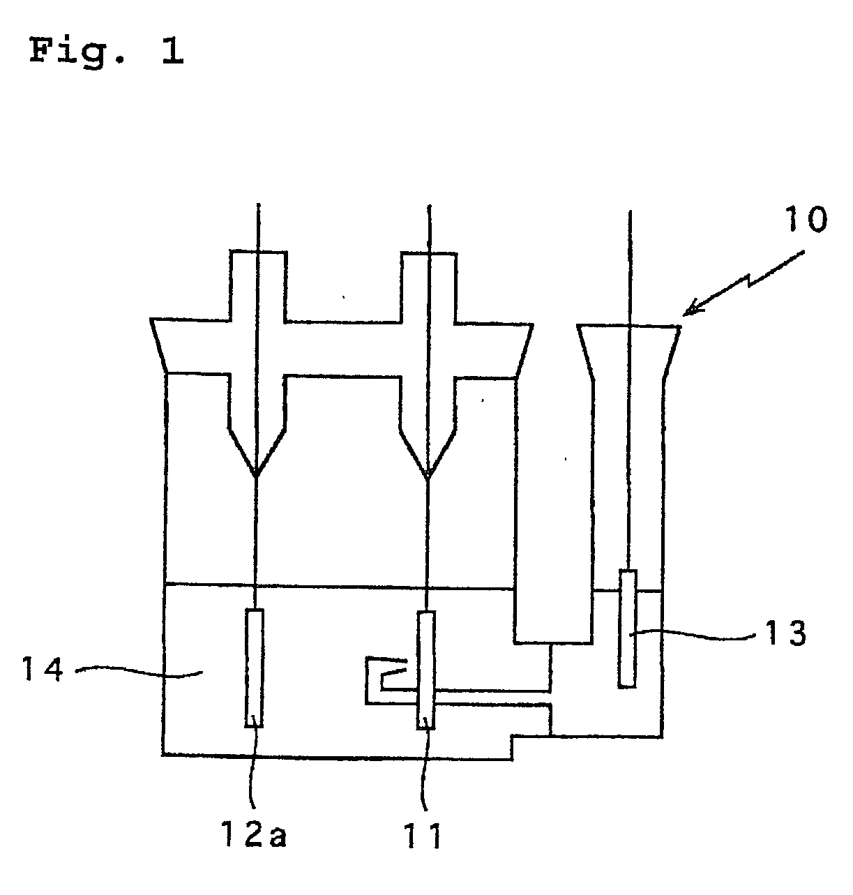
[0038] As shown in FIG. 3, the non aqueous electrolyte 14 was poured in a test cell container 10, the negative electrode 12 prepared above as a working electrode, a posit...

example 3

[0042] In this example, a non aqueous electrolyte in which LiN(CF.sub.3SO.sub.2).sub.2 as a lithium salt was added in an amount of 1 mol / l to trimethyloctyl ammonium.trifluoromethanesulfonimide ((CH.sub.3).sub.3N.sup.+(C.sub.8H.sub.17) N.sup.-(CF.sub.3SO.sub.2).sub.2-) as a room temperature molten salt was also used.

[0043] Silicon was used as a material for a negative electrode that is capable of occluding and discharging cations to prepare a negative electrode. An amorphous silicon coating was formed by sputtering on the surface of a copper film, which surface was treated by electrolysis, to prepare the negative electrode of 2 cm.times.2 cm.

[0044] As shown in FIG. 3, a test cell was prepared in the same manner as Example 2 except that the negative electrode was prepared above was used. The non aqueous electrolyte 14 was poured in a test cell container 10, the negative electrode 12 prepared above was used as a working electrode. Lithium metal was used for the positive electrode 11a ...


PUM


Abstract

A non aqueous electrolyte secondary battery comprises a positive electrode made from a material which is capable of occluding and discharging anions, a negative electrode made from a material which is capable of occluding and discharging cations, and a non aqueous electrolyte containing a room temperature molten salt having a melting point of not greater than 60° C.

Description

[0001] The present invention relates to a non aqueous electrolyte secondary battery. Especially, the invention is characterized as an improvement in a non aqueous electrolyte which makes it possible to inhibit decomposition of the electrolyte and increase fire retardancy of the battery.[0002] A non aqueous electrolyte secondary battery having high electromotive force in which there is a non aqueous electrolyte and lithium ions transfer between a positive electrode and a negative electrode has recently been utilized as a new type high output and high energy secondary battery.[0003] In such a non aqueous electrolyte secondary battery, a lithium transition metal composite oxide such as LiCoO.sub.2 has been used as the positive electrode, a carbon material which is capable of occluding and discharging lithium metal, a lithium alloy or lithium has been used as the negative electrode, and an organic solvent, such as ethylene carbonate and diethyl carbonate, which dissolves a solute compri...

Claims


Application Information

Patent Timeline
IPC IPC(8): H01M4/38H01M4/587H01M10/05H01M10/052H01M10/0568H01M10/0569H01M10/08
CPCH01M4/133H01M4/38Y02E60/122H01M10/0525H01M2300/0022H01M4/583Y02E60/10
Inventor MIYAKE, MASAHIDEFUJIMOTO, MASAHISAKOGA, HIDEYUKITARUI, HISAKIFUJITANI, SHINKIDA, YOSHINORI
Owner SANYO ELECTRIC CO LTD
Why Eureka
Try Eureka