Propulsion-Release Safety Vacuum Release System

a vacuum release and safety technology, applied in the field of fluid handling, can solve the problems of air within the circulation system of the swimming pool, the victim cannot be removed from the suction outlet, and the prime is lost, and achieves the effect of eliminating the built-in suction hazards, easy retrofitting, and convenient design

Inactive Publication Date: 2003-06-12
COHEN JOSEPH D +1
View PDF5 Cites 100 Cited by
  • Summary
  • Abstract
  • Description
  • Claims
  • Application Information

AI Technical Summary

Benefits of technology

[0013] A related object of the invention is to provide a system that reliably releases and pushes away an entrapped victim by creating a substantial pressurized incoming flow stream at the suction outlet fitting.
[0014] Optionally, another object is to provide an SVRS that performs the safety function of releasing an entrapped bather without stopping the operation of the swimming pool circulation system.
[0018] Another object of the invention is to provide an SVRS that is easily designed into a new swimming pool before construction.
[0019] Another object of the invention is to provide an SVRS that can be easily retrofitted to an existing swimming pool to eliminate built-in suction hazards.
[0021] Another desirable object of the invention is to provide an SVRS that can operate totally on hydraulic energy, not relying upon any electrical components, and therefore, neither prone to electrical component failure nor loss of electrical power to the SVRS.
[0025] The flow-reversing means is designed to make a smooth transition between the two flow patterns without stoppage of flow or abrupt pressure changes.

Problems solved by technology

All three types of SVRS release the entrapped victim but provide no adequate means to remove the victim from the suction outlet fitting.
Air within a swimming pool circulation system is a problem, as it causes the pump to lose prime and must be released manually before the system can be returned to operation.

Method used


Image

  • Propulsion-Release Safety Vacuum Release System
  • Propulsion-Release Safety Vacuum Release System
  • Propulsion-Release Safety Vacuum Release System

Examples


Embodiment Construction

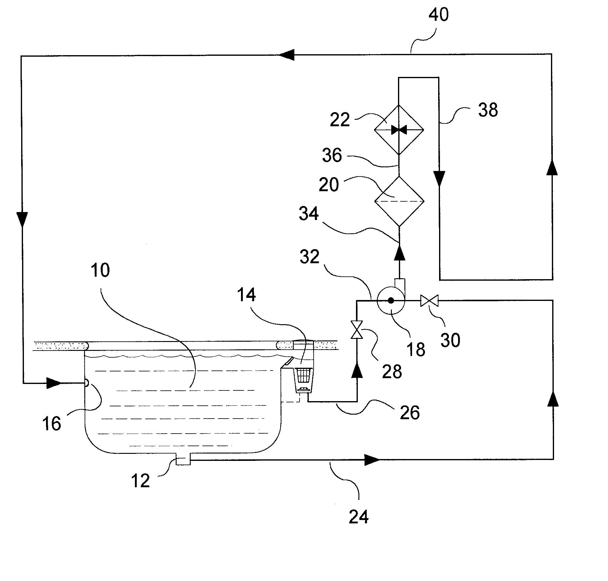
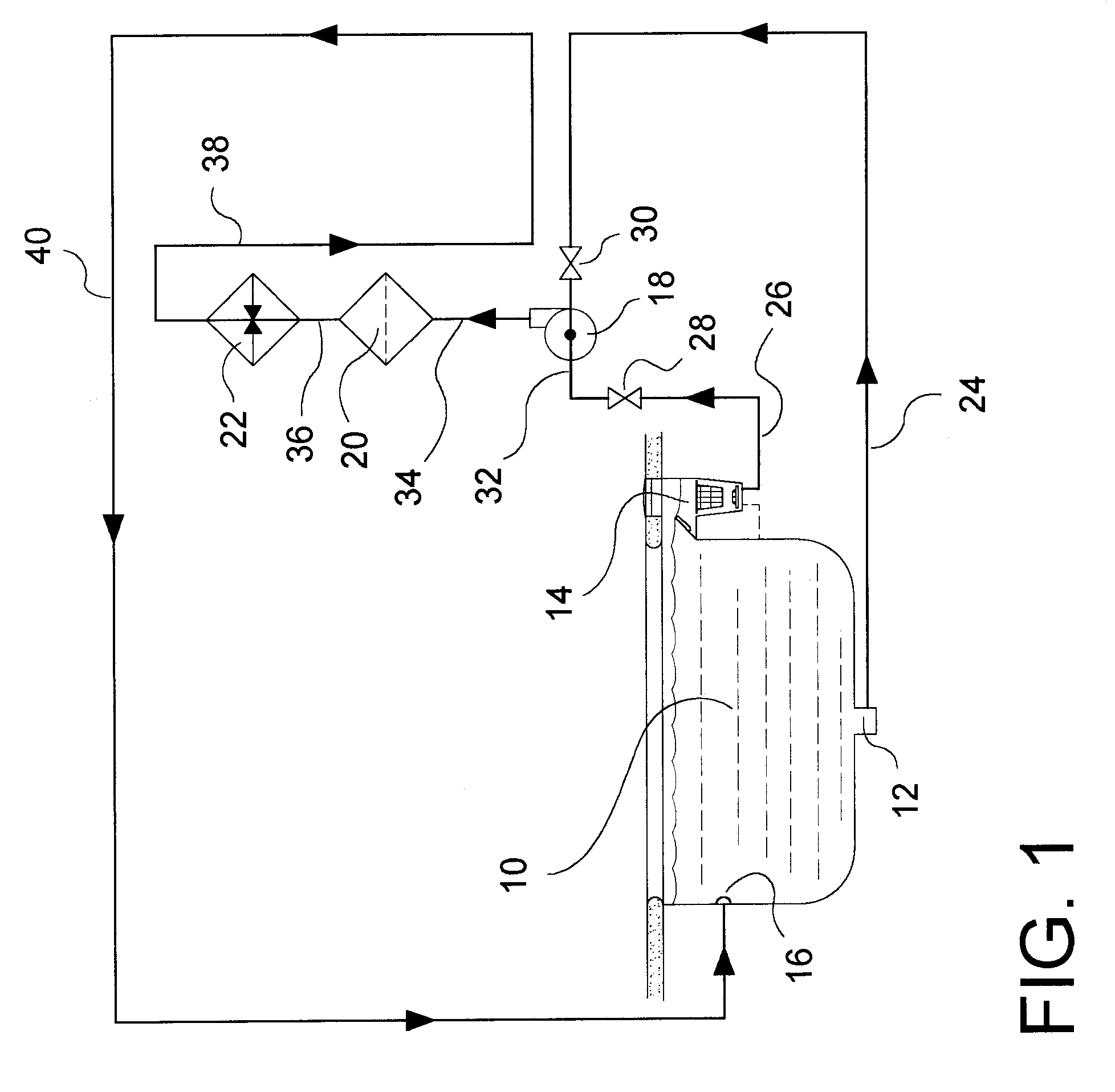
[0035] The following item numbers are used in the drawings to identify the elements of the invention and are used throughout the following description:

[0036] Swimming pool components:

[0037] 10 Pool

[0038] 12 Pool Main Drain

[0039] 14 Pool Surface Skimmer

[0040] 16 Pool Surface Return

[0041] 18 Pump

[0042] 20 Filter

[0043] 22 Heater

[0044] Circulation system components:

[0045] 24 Pool Drain Line

[0046] 26 Pool Skimmer Line

[0047] 28 Skimmer Control Valve

[0048] 30 Drain Control Valve

[0049] 32 Main Pump Suction Line

[0050] 34 Pump Discharge Line

[0051] 36 Filter Effluent Line

[0052] 38 Support System Effluent Line

[0053] 40 Pool Return Line

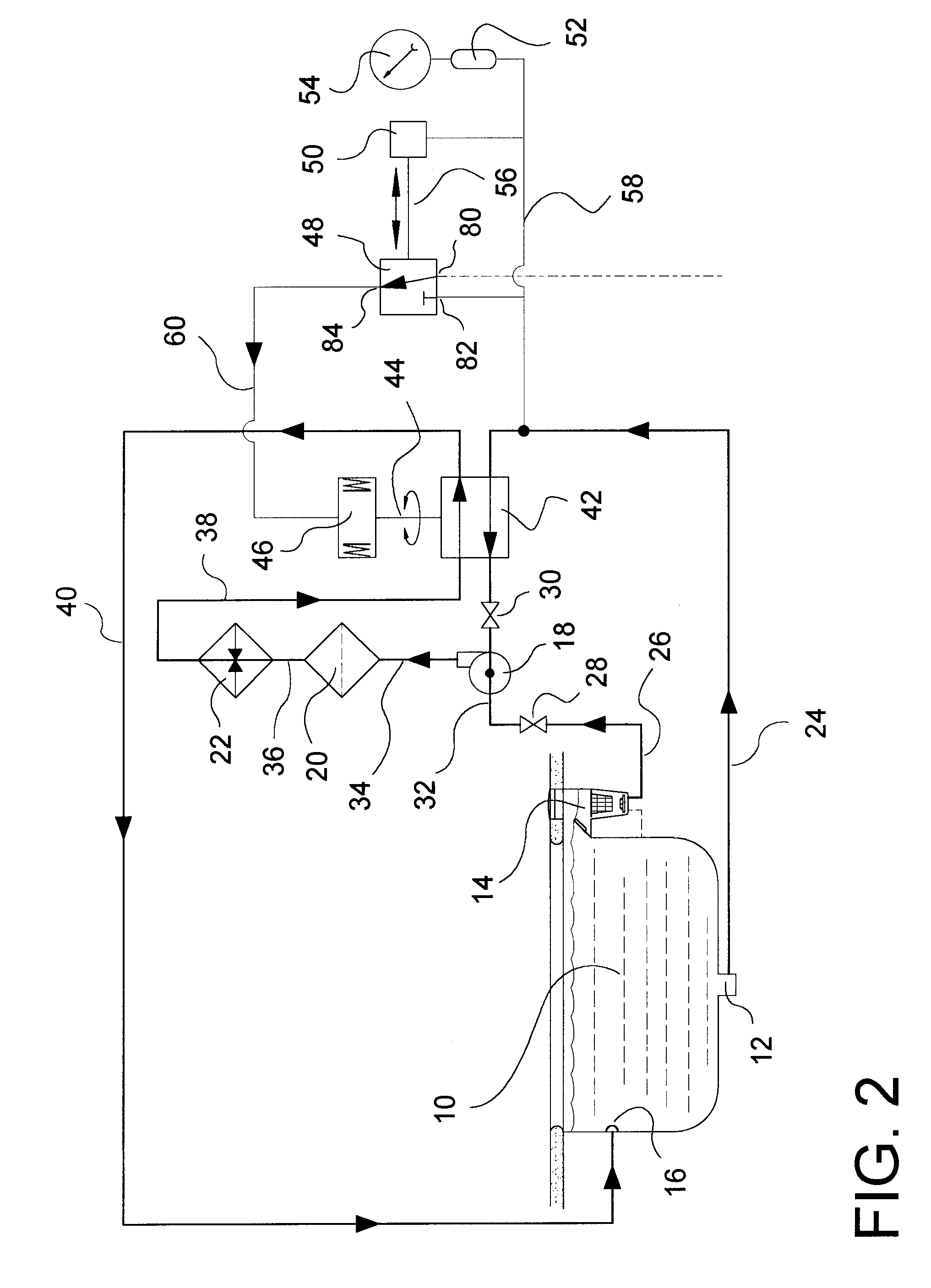
[0054] Propulsion-release safety vacuum release system (SVRS) components:

[0055] 42 Four-Port Multi-port Flow Reversing Valve

[0056] 44 Reversing Valve Actuator Shaft

[0057] 46 Hydraulic Valve Actuator

[0058] 48 Directional Control Valve

[0059] 50 Flow Blockage Suction Interrupter Valve (FBSI)

[0060] 52 Suction Spike Arrester

[0061] 54 Vacuum / Pressure Gauge

[0062] 56 FB...


PUM


Abstract

Abstract of Disclosure A propulsion-release safety vacuum release system (SVRS) for swimming pools monitors vacuum level in a suction pipe and reverses flow within the suction pipe if vacuum level exceeds a predetermined level. Thus, if a bather becomes entrapped on a suction outlet such as the pool main drain, the SVRS system not only releases the vacuum but also pushes away the suction-entrapped bather. In response to an elevated vacuum level, a vacuum-monitoring device actuates an automatic valve, which reverses fluid communications between the influent and effluent conduits of the pump and filter system. In this process, the suction pipe is converted from vacuum (negative pressure) to positive pressure. Thereafter, the automatic valve system automatically resets the SVRS to the original or normal flow configuration. The SVRS functions without interrupting operation of the swimming pool filtration system.

Description

Cross Reference to Related Applications[0001] This application claims the benefit of United States Provisional Patent Application Serial No. 60 / 337,893 filed December 10, 2001, pending.Background of Invention[0002] Field of the Invention -- In one aspect, the invention generally relates to fluid handling. More specifically, it relates to the use of line condition change responsive valves. In a second aspect, the invention generally relates to pool type baths. More specifically, it discloses a method of utilizing a flow control valve to prevent vacuum entrapment against suction fittings in swimming pools, wading pools, and hydrotherapy pools. Further applications include any pump suction system that would benefit from a method of automatically clearing a suction intake of blockages.[0003] Description of Prior Art -- A number of inventions provide protection to bathers who become entrapped onto a suction outlet fitting in a swimming pool. These devices are categorized as safety vacuum...

Claims


Application Information

Patent Timeline
Patent Type & Authority Applications(United States)
IPC IPC(8): E04H4/12
CPCE04H4/12
Inventor COHEN , JOSEPH D.KRUMHANSL , MARK URBAN
Owner COHEN JOSEPH D
Why Eureka
Try Eureka