Control device to achieve variable compression ratio for triangle rotary engine

a control device and rotary engine technology, applied in the direction of engines, mechanical equipment, machines/engines, etc., can solve the problems of increasing the mechanical load of the engine, reducing the reliability and service life of the engine, and the turbocharging system not working, so as to achieve the optimal compression ratio and improve the performance of the rotary engine. significant

Active Publication Date: 2019-01-10
JIANGSU UNIV
View PDF4 Cites 1 Cited by
  • Summary
  • Abstract
  • Description
  • Claims
  • Application Information

AI Technical Summary

Benefits of technology

[0014]The actuator of the present invention which can achieve variable compression ratios for rotary engine, can be controlled by the control system, to provide the optimal compression ratio according to the compression ratio requirements on the different working conditions. Therefore, the invention can make the rotary engine always work in the best compression ratio under different working conditions, and the performance of the rotary engine can be improved significantly.

Problems solved by technology

This is due to the fact that the design parameters of the total cylinder volume and combustion chamber volume are fixed and cannot be changed in the working process.
However, the oversized compression ratio will increase the engine's mechanical load, heat load and the possibility of detonation.
In addition, the oversized compression ratio will also reduce the reliability and service life of the engine.
That is, under the condition of low engine speed, turbocharging system does not work.
Therefore, compared with the natural aspirated engine, the torque rise of the turbo-supercharged engine is slow at low speed.
In addition, the engine's mechanical load and heat load are increased, and the reliability of the engine is also very unfavorable.

Method used


Image

  • Control device to achieve variable compression ratio for triangle rotary engine
  • Control device to achieve variable compression ratio for triangle rotary engine
  • Control device to achieve variable compression ratio for triangle rotary engine

Examples


Embodiment Construction

[0024]Hereunder the embodiments of the present invention will be described in detail with reference to the accompanying drawings.

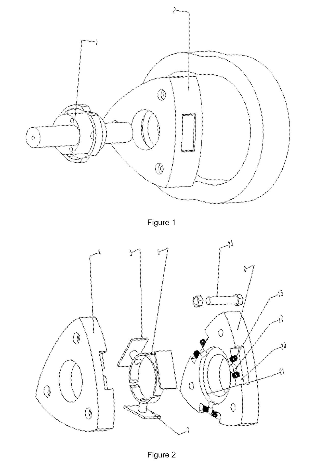
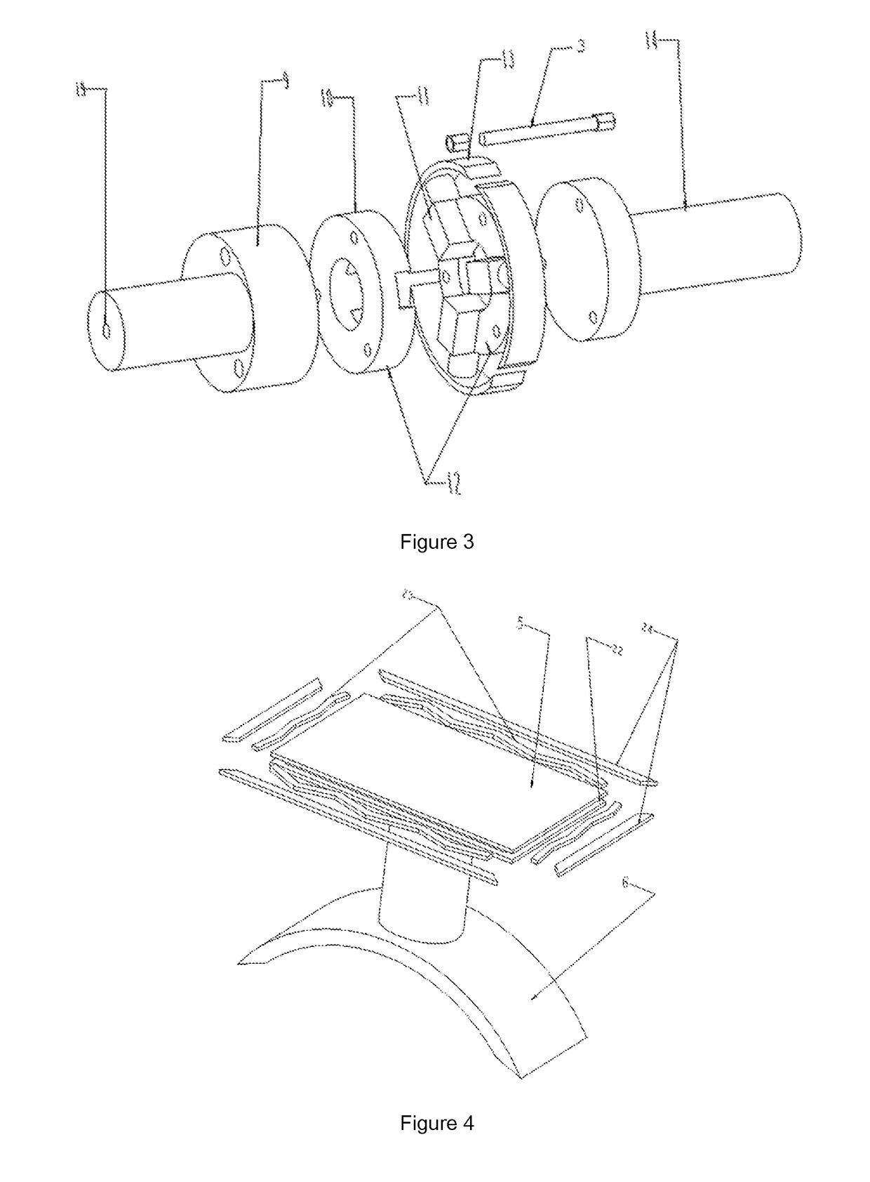
[0025]Combining FIG. 1, FIG. 2, FIG. 3 and FIG. 7, the actuator which can achieve different compression ratios for rotary engine, includes three parts: the eccentric shaft part 1, the triangle rotor part 2 and the control system.

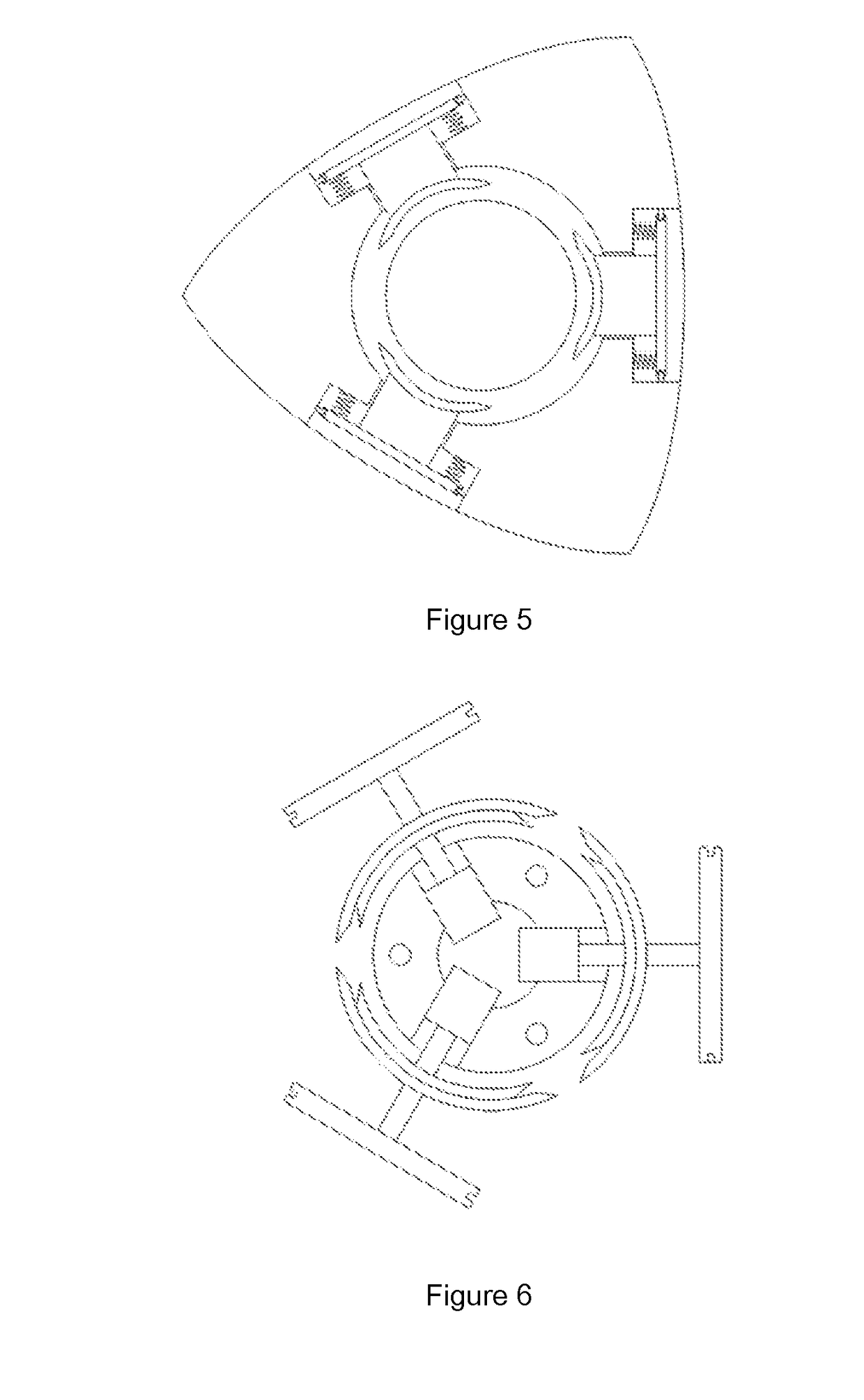
[0026]The eccentric shaft part 1 which is described above, includes the front part of the eccentric shaft 9, the combination of electric three jaw 12 and the rear part of the eccentric shaft 14. The combination of electric three jaw 12 which is described above, includes the end cap of the electric three-jaw 10 and the electric three-jaw 11. The telescopic distance of the claw top of the electric three jaw 11 is controlled by the electric three jaw 11, by using the control system described above. Each claw top of the electric three jaw 11 which is described above, is fitted with the inner support arc block 13. The front part of the ...


PUM


Abstract

The present invention provides an actuator that can realize the different compression ratios of the rotary engine. The invention actuator described above, includes three parts: the eccentric shaft part, the triangle rotor part and the control system. The eccentric shaft part which is described above, includes the front part of the eccentric shaft, the combination of electric three jaw and the rear part of the eccentric shaft. The triangle rotor part which is described above, includes the variable volume actuator, the front part of the rotor and the rear part of the rotor. The control system which is described above, includes the control system of electric three jaw and the rotating joint. The expansion and contraction of the electric three jaw described above, are controlled by the control system of electric three jaw described above. The eccentric shaft part described above passes through the triangle rotor part described above, to make the combination of electric three jaw to arrange in the annular groove described above. The reciprocating motion of the variable volume actuator described above, is controlled by the expansion and contraction of the claw top of the electric three-jaw. The invention can adjust the engine compression ratio through the whole compression ratio adjustment system, to make the rotary engine always work in the best compression ratio under different working conditions. Therefore, the invention can improve the performance of rotary engine significantly.

Description

TECHNICAL FIELD[0001]The invention relates to the technical field of a dynamic mechanical system. Especially, the invention relates to an actuator that can achieve different compression ratios for rotary engine (Wankel engine).BACKGROUND ART[0002]The compression ratio is the ratio of the total cylinder volume to the combustion chamber volume of an engine. It is an important parameter used to control combustion, detonation and emission of an engine. It is also an important parameter in the design field of the internal combustion engine. Generally speaking, the compression ratio of the traditional engine is not changeable. This is due to the fact that the design parameters of the total cylinder volume and combustion chamber volume are fixed and cannot be changed in the working process. It is known that increasing the compression ratio can improve the indicated thermal efficiency of the engine, improve the engine power, improve engine economy, improve engine emission performance, as we...

Claims


Application Information

Patent Timeline
Patent Type & Authority Applications(United States)
IPC IPC(8): F01C20/18F02D15/04F02B55/02F02B53/02F01C21/08F01C19/00
CPCF01C20/18F02D15/04F02B55/02F01C2021/1606F01C21/08F01C19/00F02B53/02F01C21/00F01C1/22F01C20/20Y02T10/12
Inventor FAN, BAOWEIPAN, JIANFENGLU, YAOCHEN, WEI
Owner JIANGSU UNIV
Why Eureka
Try Eureka