
Recorder

a recording device and recording technology, applied in the field of recording devices, can solve the problems of shortened recording intervals of image signals, poor cost performance, and prior art giving rise to a cost problem

Inactive Publication Date: 2003-06-12
SANYO ELECTRIC CO LTD
View PDF5 Cites 16 Cited by
  • Summary
  • Abstract
  • Description
  • Claims
  • Application Information

AI Technical Summary

Benefits of technology

[0007] Therefore, it is a primary object of the present invention to provide a recording apparatus capable of restraining a capacity of the recording medium, and recording the image signals at a high frame rate even before the alarm signal is generated.

Problems solved by technology

However, recording intervals of the image signals are shortened in response to the generation of the alarm signal, and therefore, there was a slight possibility that important evidence is not retained when no alarm signal is generated.
However, this prior art gave rise to a problem in terms of a cost due to a fact that the frame rate is so high that a huge amount of the ring buffer memory was needed.
However, in the disk recording medium, there is a possibility that a fragment in a vacant area reduces an effective recording rate, thereby destructing a recording process.
Furthermore, if it is attempted to equalize the recording frame rate before and after the alarm signal is generated, and retain many recording capacities of the image signals before the alarm signal is generated, the recording capacity of the image signals after the alarm signal is generated relatively deteriorates.
In order to record the image signals after the alarm signal is generated for long hours, it is needed to increase a total capacity of the disk recording medium, thus giving rise to the cost problem as described above.

Method used


Image

  • Recorder
  • Recorder
  • Recorder

Examples


Embodiment Construction

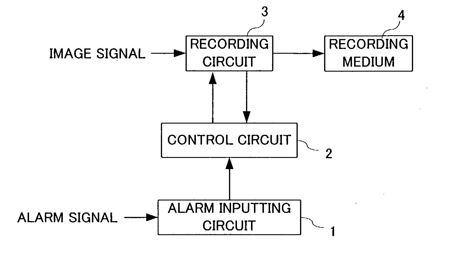
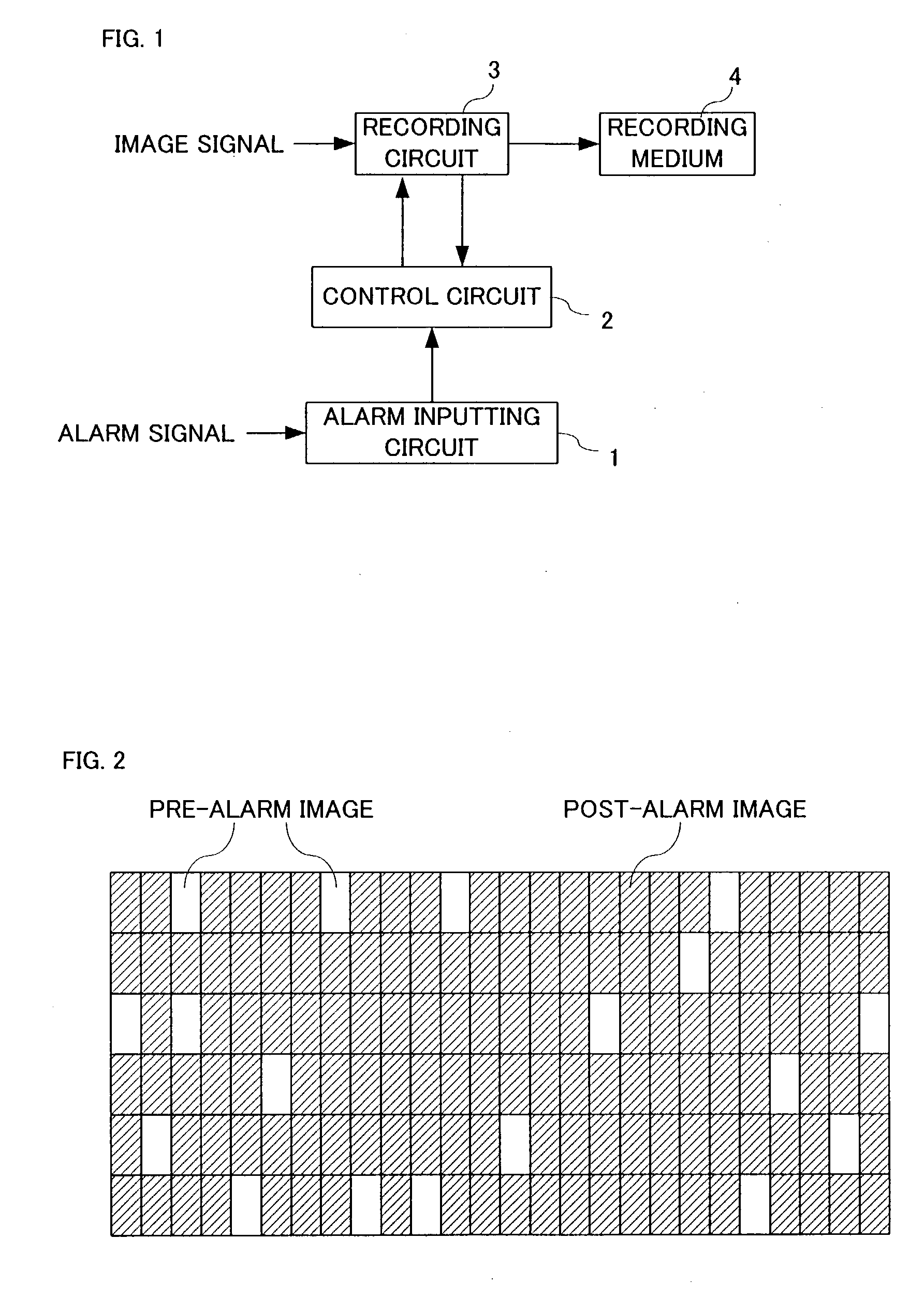
[0026] Referring to FIG. 1, a recording apparatus in this embodiment includes an alarm inputting circuit 1 for inputting an alarm signal. The alarm signal is output from an image processing apparatus (not shown) in response to a luminance change of image signals produced by an illegal invasion by a suspicious person, for example. A control circuit 2 controls a recording circuit 3 on the basis of the alarm signal applied via the alarm inputting circuit 1 and a vertical synchronization signal output from the recording circuit 3. In addition to outputting the vertical synchronization signal multiplexed on the image signals to the control circuit 2, the recording circuit 3 intermittently selects the image signals in response to a control signal applied from the control circuit 2, and records the selected image signal into a recording medium 4 in a compressed state. It is noted that the image signals are input from a surveillance camera (not shown).

[0027] As for the recording medium 4, i...


PUM


Abstract

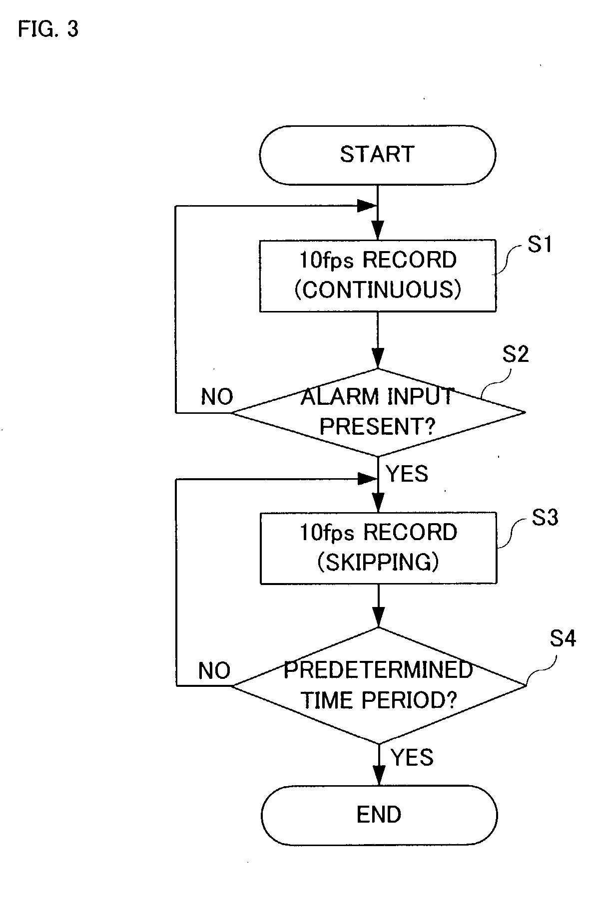
A recording apparatus includes a recording medium 4 formed with a plurality of unit memory areas thereon. When no alarm signal is generated, a recording circuit 3 writes image signals into the unit memory areas in a cyclical manner. When the alarm signal is generated, the recording circuit 3 overwrites the image signals into the unit memory areas, which are intermittently present. Although a frame rate of the image signals at a time of writing is always 10 fps irrespective of the alarm signal, one portion of the image signals written before generating the alarm signal is deleted by the overwriting, which is after generating the alarm signal. The frame rate of the image signal that is remained as a result of not being overwritten decreases to 2 fps.

Description

[0001] The present invention relates to a recording apparatus. More specifically, the present invention relates to a recording apparatus that is applied to a surveillance camera system, for example, and records in a cyclical manner image signals output at intervals of a predetermined period from the surveillance camera into a plurality of unit areas formed in a recording medium.PRIOR ART[0002] In order to monitor an illegal act, an illegal intruder or the like, a surveillance camera is installed in a casino, a factory, a shop, and the like. Image signals output from the surveillance camera are applied to a time lapse VCR via a multiplexer, thereby being recorded into a recording medium intermittently. As for a recording method of the image signals, there are various methods, that is, one of which always records the image signals irrespective of whether or not a trouble occurs, another of which generates an alarm signal in response to a luminance change of the image signals as a resu...

Claims


Application Information

Patent Timeline
Patent Type & Authority Applications(United States)
IPC IPC(8): H04N5/915G08B13/196G08B15/00G08B25/00H04N5/76H04N7/18
CPCG08B13/19667G08B13/19669H04N7/188H04N5/76H04N7/18G08B13/19676
Inventor SUNAGAWA, OSAMI
Owner SANYO ELECTRIC CO LTD
Learn More