Aerosol generator having heater arranged to vaporize fluid in fluid passage between bonded layers of laminate

a technology of aerosol generator and heater, which is applied in the direction of heating types, lighting and heating apparatus, and containers discharging methods, etc. it can solve the problems of complex manufacturing and assembly of such aerosol generators, and the inability of aerosol generators suited for delivering medicated materials to deliver such high flow rates,

Inactive Publication Date: 2003-06-12
PHILIP MORRIS USA INC
View PDF41 Cites 136 Cited by
  • Summary
  • Abstract
  • Description
  • Claims
  • Application Information

AI Technical Summary

Problems solved by technology

Most known aerosols suited for delivering medicated material are incapable of delivering material at such high flow rates while maintaining a suitable average mass median particle diameter.
In addition, most known aerosol generators deliver an imprecise amount of aerosol compared with the amount of aerosol that is intended to be delivered.
However, since these aerosol generators employ heat-generating systems, heat resistive material and, in some cases, various control devices, pumps and valves, the manufacture and assembly of such aerosol generators can be complicated and expensive.

Method used


Image

  • Aerosol generator having heater arranged to vaporize fluid in fluid passage between bonded layers of laminate
  • Aerosol generator having heater arranged to vaporize fluid in fluid passage between bonded layers of laminate
  • Aerosol generator having heater arranged to vaporize fluid in fluid passage between bonded layers of laminate

Examples


Embodiment Construction

[0016] When referring to the drawing figures, like reference numerals designate identical or corresponding elements throughout the several figures.

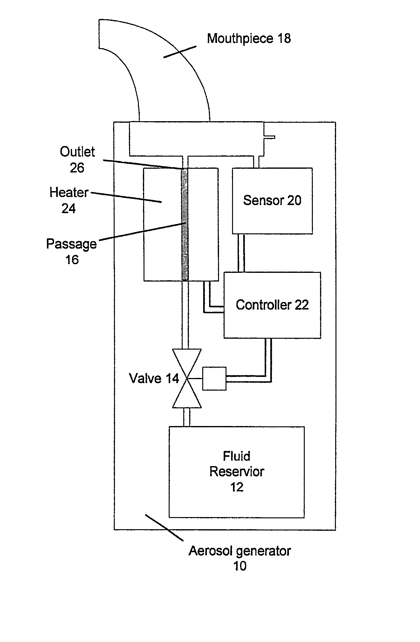
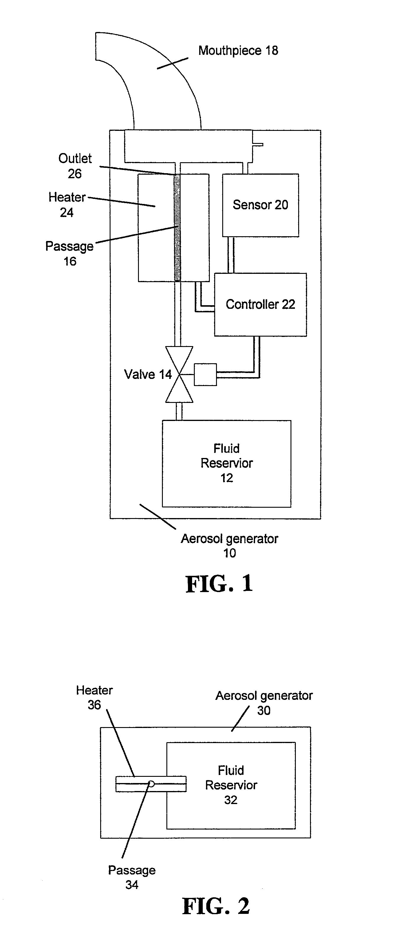
[0017] FIG. 1 shows a vapor driven aerosol generator 10 in accordance with one embodiment of the invention. As shown, the aerosol generator 10 includes a source 12 of fluid, a valve 14, a passage 16, a mouthpiece 18, an optional sensor 20 and a controller 22. In addition, the aerosol generator 10 includes a heater 24. The controller 22 includes suitable electrical connections and ancillary equipment such as a battery which cooperates with the controller for operating the valve 14, the sensor 20 and the heater 24. In operation, the valve 14 can be opened to allow a desired volume of fluid from the source 12 to enter the passage 16 prior to or subsequent to detection by the sensor 20 of vacuum pressure applied to the mouthpiece 18 by a user attempting to inhale aerosol from the inhaler 10. As fluid is supplied to the passage 16, the control...


PUM


Abstract

An aerosol generator includes a fluid supply which supplies fluid to a fluid passage and a heater which heats the fluid into a gaseous state, the fluid passage being located between opposed layers of a laminate. The fluid passage can be a capillary sized passage formed by locating a mandrel between opposed layers of the laminate, bonding the layers together and removing the mandrel such that the space previously occupied by the mandrel forms the fluid passage. The opposed layers of the laminate can be copper sheets and ceramic layers can be provided on the outside of the copper layers. The aerosol generator can be used to generate aerosols containing medicated materials.

Description

[0001] 1. Field of the Invention[0002] The present invention relates generally to aerosol generators and, more particularly, to vapor driven aerosol generators. The aerosol generators of the invention are able to generate aerosols without requiring the use of compressed gas propellants. The present invention also relates to methods for generating an aerosol. The present invention has particular applicability to the generation of aerosols containing medicated material.[0003] 2. Description of the Related Art[0004] Aerosols are gaseous suspensions of fine solid or liquid particles and are useful in a wide variety of applications. For example, medicated liquids and powders may be administered in aerosol form. Such medicated aerosols include, for example, materials which are useful in the treatment of respiratory ailments, in which case the aerosols may be inhaled into a patient's lungs. Aerosols may also be used in non-medicinal applications including, for example, dispensing air fresh...

Claims


Application Information

Patent Timeline
Patent Type & Authority Applications(United States)
IPC IPC(8): A61M11/04A61M15/00B05B17/04
CPCA61M11/041A61M15/00A61M11/007A61M11/042B05B17/04A61M15/025
Inventor SHERWOOD, TIMOTHY S.SOWERS, SCOTT A.REDDY, SIRISHA P.SPRINKEL, F. MURPHY JR.COX, KENNETH A.NICHOLS, WALTER A.
Owner PHILIP MORRIS USA INC
Why Eureka
Try Eureka