Electric connection box

a technology of electrical connection box and connection box, which is applied in the direction of electrical apparatus casing/cabinet/drawer, coupling device connection, hermetically sealed casing, etc., can solve the problems of difficult operation and large time and labor required for disassembly operation

Inactive Publication Date: 2003-06-12
AUTONETWORKS TECH LTD +2
View PDF11 Cites 12 Cited by
  • Summary
  • Abstract
  • Description
  • Claims
  • Application Information

AI Technical Summary

Problems solved by technology

On the other hand, when the junction box is in use, a predetermined force of connection between the cover and the body is required, and therefore lock mechanisms are provided respectively at a plurality of portions to increase

Method used


Image

  • Electric connection box
  • Electric connection box
  • Electric connection box

Examples


first embodiment

[0022] (First Embodiment)

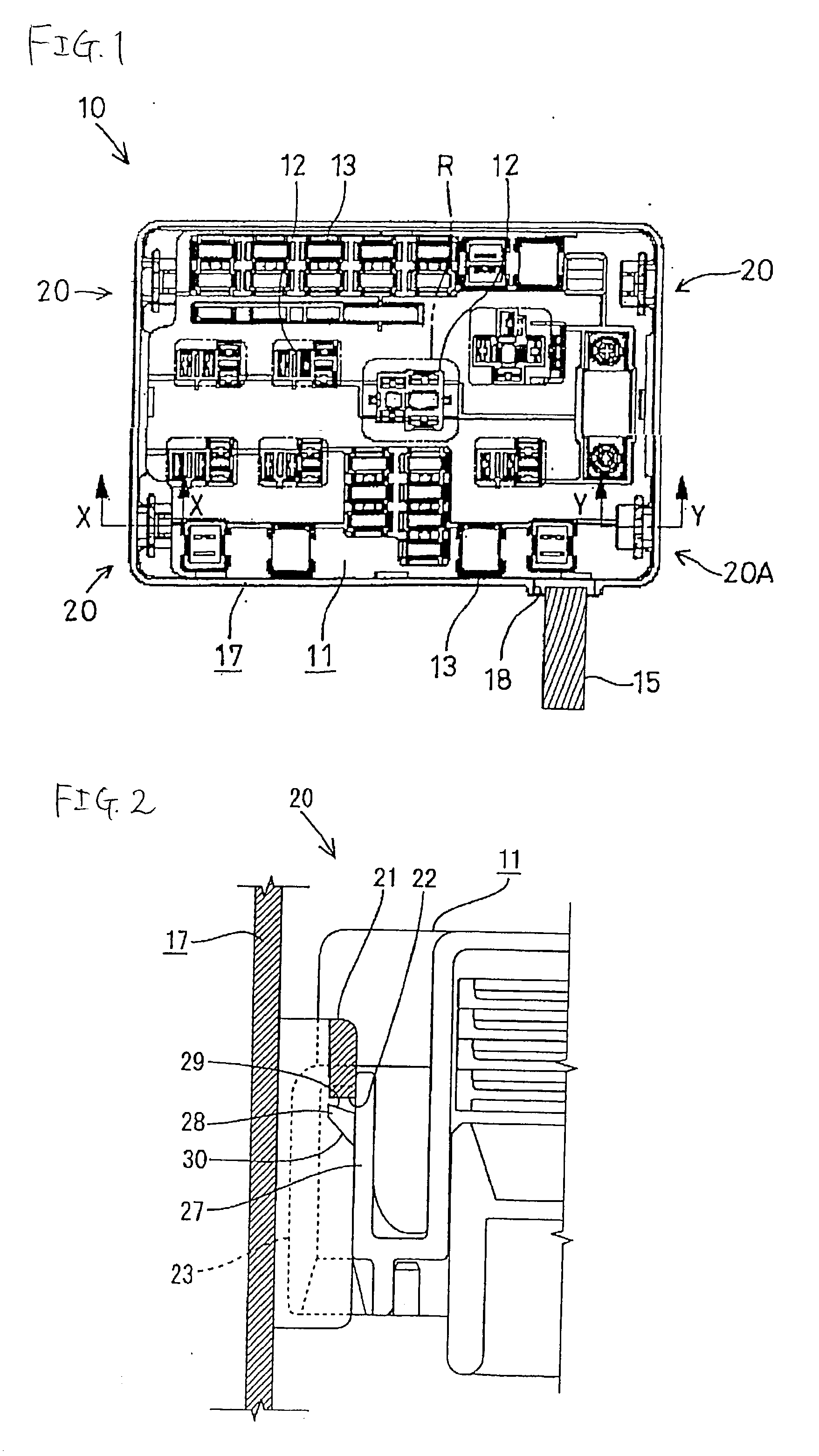
[0023] A first embodiment of the present invention will be described with reference to FIGS. 1 to 5. In this embodiment, the invention is applied to a junction box 10 (hereinafter referred to as "J / B").

[0024] As shown in FIG. 1, the J / B 10 of this embodiment comprises a body 11, and a cover 17 attached to a lower surface of this body 11. Each of the body and the cover is made of a synthetic resin.

[0025] The body 11 has a substantially rectangular shape when viewed from the top. A relay mounting portion 12 for mounting a relay R is provided at a central portion of the upper surface of the body 11, and fuse mounting portions 13 for mounting various fuses (mini-fuses, fusible links and soon) are provided at both sides of the relay mounting portion. Within the body 11, wires, connected respectively to the mounting portions 12 and 13, are bundled into a single wire harness 15 (hereinafter referred to as "W / H"), and this wire harness is extended downwardly (in FIG...

second embodiment

[0036] (Second Embodiment)

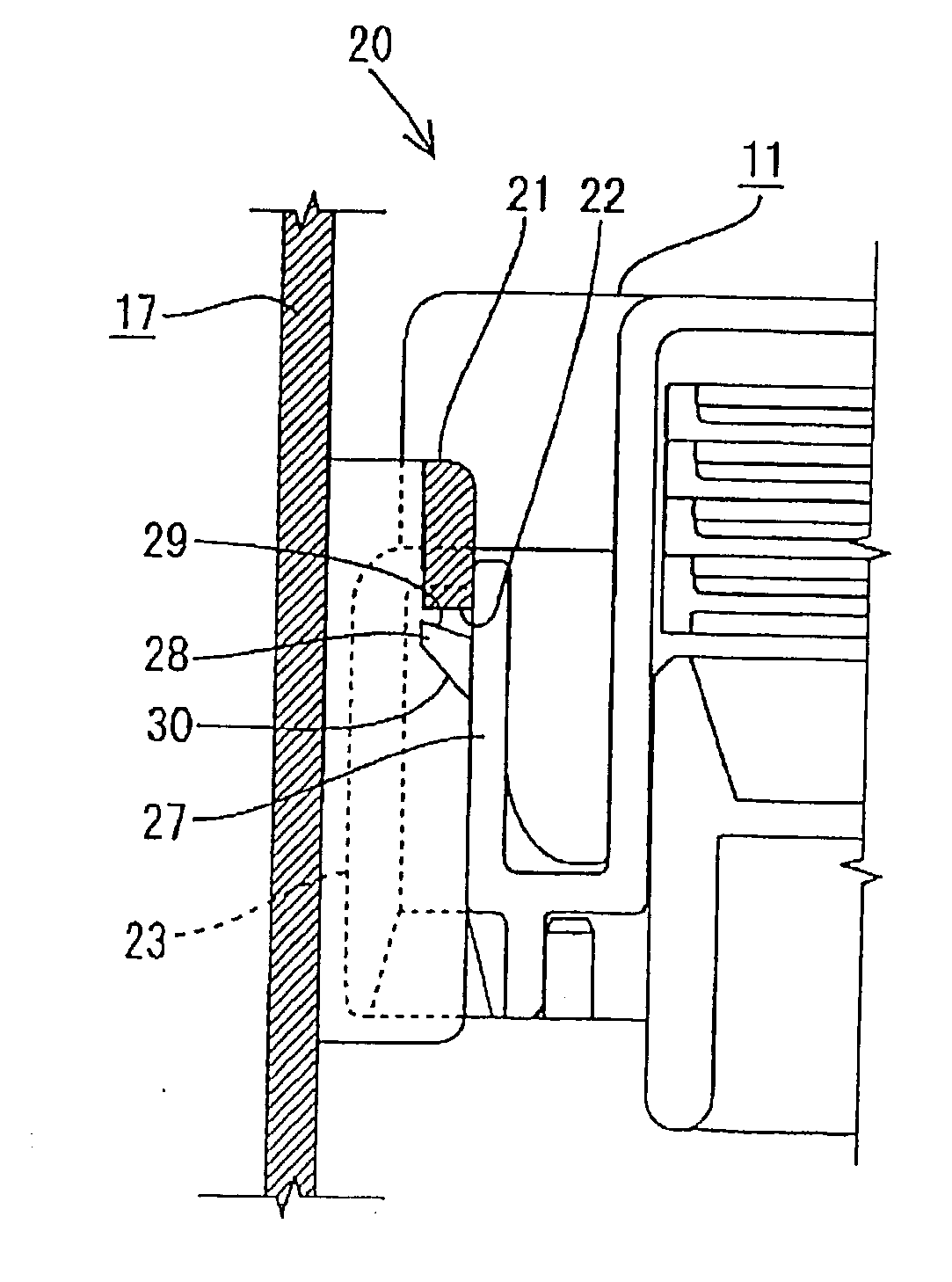
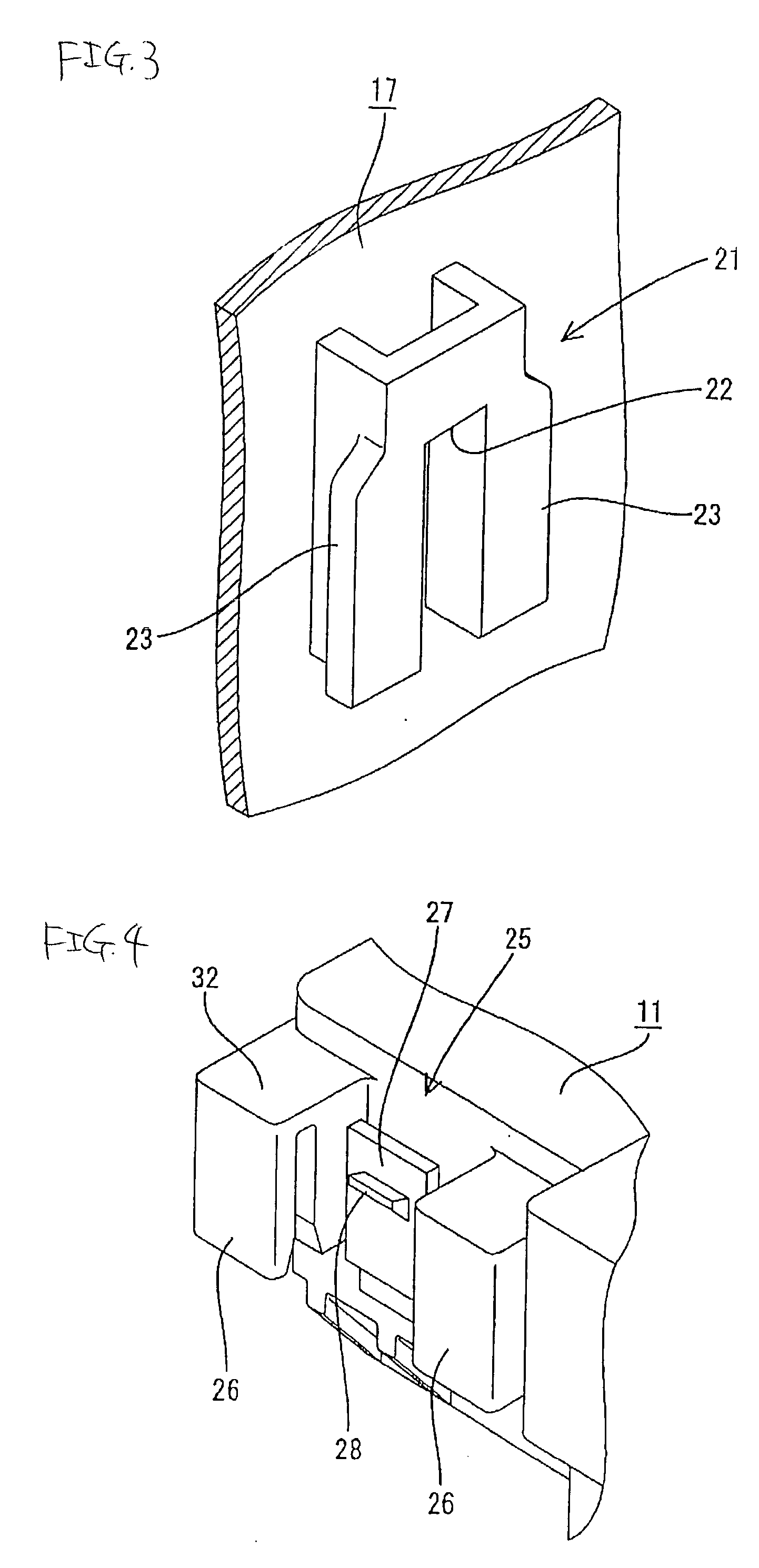
[0037] A second embodiment of the present invention will be described with reference to FIG. 6. In a lock mechanism 20B of this embodiment, disposed near to a position where a W / H 15 is extended outwardly, a lock piece portion 27B first projects outwardly from an outer surface of a body, and then is bent at right angles to extend downwardly. This lock piece portion 27B has a downwardly-directed cantilever-shape, and is elastically deformable. A projection 28, formed on the lock piece portion 27B, has an upper surface serving as an overhanging retaining surface 29, while its lower surface serves as a tapering guide surface 30.

[0038] The other structure is the same as that of the first embodiment, and those portions, having the same functions as those in the first embodiment, will be designated by identical reference numerals, respectively, and repeated description will be omitted.

[0039] In this embodiment, when the W / H 15 is gripped and pulled so as to remov...


PUM


Abstract

An electric connection box includes a cover fitted on a lower side of a body having mounting portions, and the cover is fixedly secured to a vehicle body. A wire harness is extended outwardly from a portion of the body, disposed near to one corner portion thereof, through an escape groove. Plural lock mechanisms, in which a lock piece portion can be elastically fitted into a lock groove, are provided at fitting peripheral surfaces of the body and cover, and are disposed near to four corner portions thereof respectively. One lock mechanism, disposed near to a position where the wire harness is extended outwardly, has a semi-lock structure, and thus has a smaller retaining force than the other lock mechanisms.

Description

[0001] 1. Field of the Invention[0002] This invention relates to an electric connection box such as a junction box.[0003] 2. Description of the Related Art[0004] One example of known junction boxes comprises a body having electrical parts (such as relays and fuses) mounted thereon, and a cover attached to a lower surface of the body. A wire harness is extended outwardly from a predetermined portion of the body. A plurality of elastically-deformable lock piece portions are formed on and project from the body, and lock portions, corresponding respectively to the lock piece portions, are formed at the cover. The lock piece portions are elastically deformed to be retainingly engaged with the lock portions respectively, thereby connecting the cover to the lower surface of the body in a united manner. This cover is fixedly secured to a vehicle body by screws.[0005] This kind of junction box is disclosed, for example, in JP-A-2001-218335.[0006] When disassembling a vehicle, such a junction...

Claims


Application Information

Patent Timeline
IPC IPC(8): H01R13/52H01R13/627B60R16/02H02G3/14
CPCH01R13/6271H01R13/5213
Inventor SAKA, YUUJIYUASA, ERIKOMIYAMUKAI, TAKAMICHIHAYASHI, HIROYUKIYONEYAMA, ISAOITO, KEIICHITSUKAMOTO, YOSHIHIDETAKAMATSU, MASAHIRONOMURA, KOJI
Owner AUTONETWORKS TECH LTD
Why Eureka
Try Eureka