Fuel injection valve

a technology of fuel injection valve and injector, which is applied in the direction of fuel injection apparatus, charge feed system, spraying apparatus, etc., can solve the problems of high cost, high precision required to prevent the development of a secondary flow path, and complicated manufacturing of the cylindrical swirl inser

Inactive Publication Date: 2003-06-19
ROBERT BOSCH GMBH
View PDF4 Cites 12 Cited by
  • Summary
  • Abstract
  • Description
  • Claims
  • Application Information

AI Technical Summary

Problems solved by technology

One disadvantage of the known fuel injectors is the complicated manufacturing of the cylindrical swirl insert.
It is expensive and time-consuming to produce the individual swirl grooves.
The high precision required to prevent the development of a secondary flow path also has a negative effect on cost.

Method used


Image

  • Fuel injection valve
  • Fuel injection valve
  • Fuel injection valve

Examples


Embodiment Construction

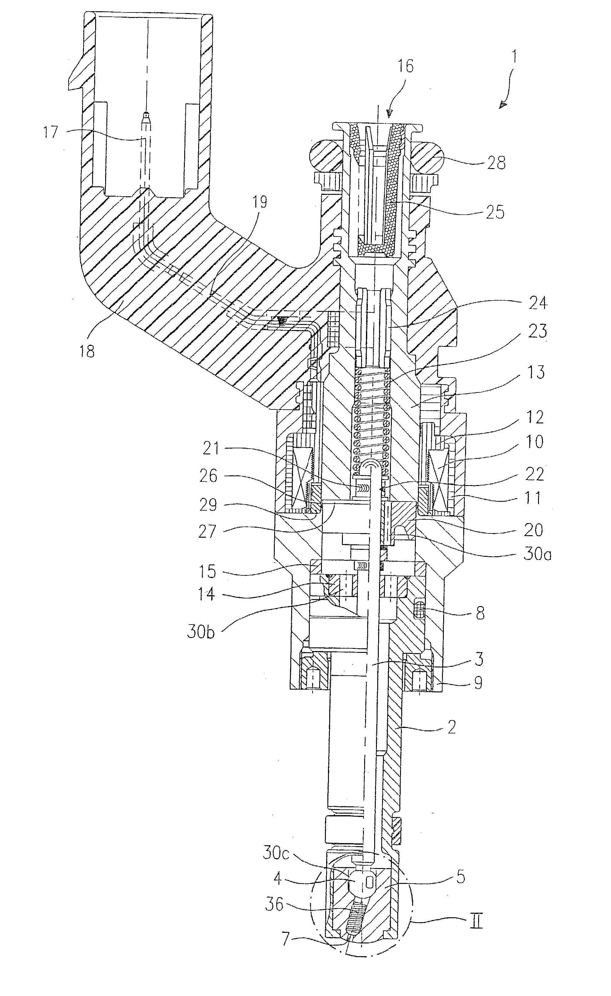
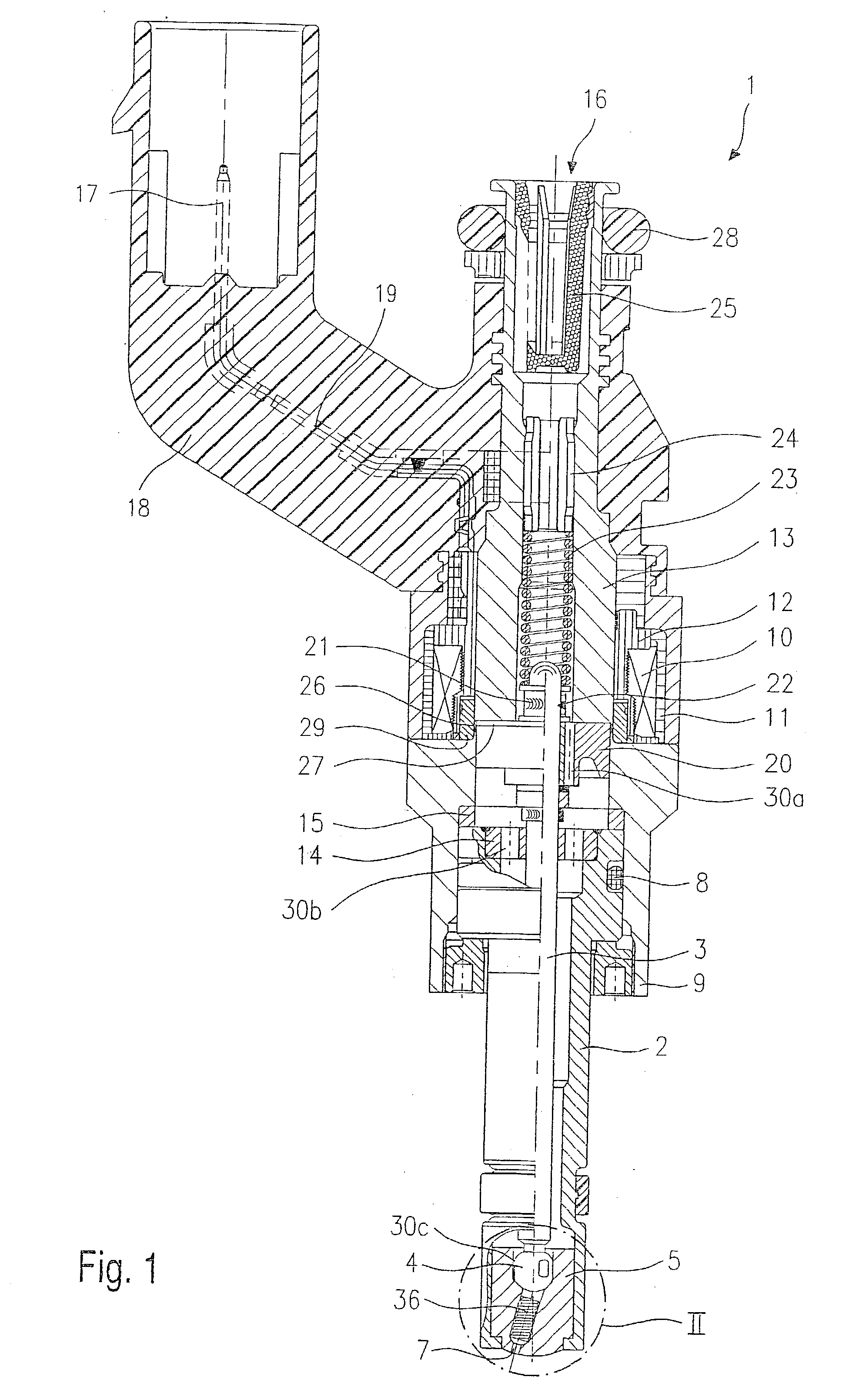
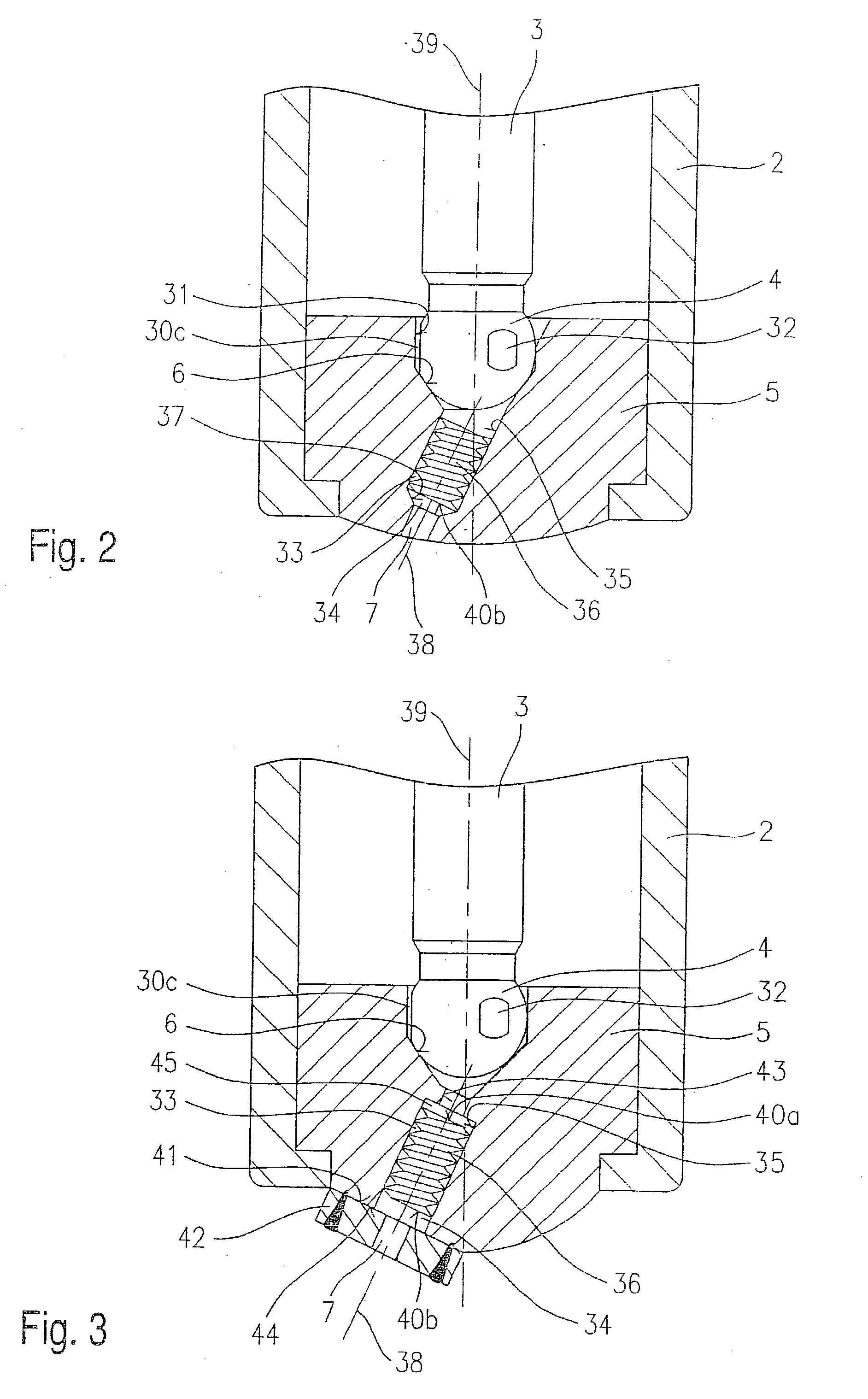
[0017] Before describing two embodiments of a fuel injector 1 in greater detail with reference to FIGS. 2 and 3, fuel injector 1 according to the present invention will first be explained briefly with respect to its essential components in an overall presentation.

[0018] Fuel injector 1 is designed in the form of a fuel injector 1 for fuel injection systems of internal combustion engines having compression of a fuel / air mixture with spark ignition. Fuel injector 1 is suitable in particular for direct injection of fuel into a combustion chamber (not show) of an engine.

[0019] Fuel injector 1 has a nozzle body 2 in which a valve needle 3 is situated. Valve needle 3 is mechanically linked to a valve-closure member 4 which cooperates with a valve-seat surface 6 situated on a valve-seat member 5 to form a sealing seat. In this embodiment, fuel injector 1 is an electromagnetically operated fuel injector 1 having an injection orifice 7. Nozzle body 2 is sealed by a gasket 8 with respect to a...


PUM


Abstract

A fuel injector (1) for fuel injector systems of internal combustion engines has a valve-closure member (4) which is mechanically linked to a valve needle (3) and cooperates with a valve-seat surface (6) of a valve-seat member (5) to form a sealing seat. A turbulence-producing element is provided in the valve-seat member (5), situated downstream from the sealing seat, and its center line (38) preferably forms an angle different from zero with the center line (39) of the fuel injector (1), a threaded rod (36) being pressed into the valve-seat member (5) as the turbulence-producing element.

Description

BACKGROUND INFORMATION[0001] The present invention relates to a fuel injector according to the preamble of the main claim.[0002] Fuel injectors having an element to produce turbulence downstream from a sealing seat are known from German Patent Application 31 21 572 A1. A cylindrical component having grooves in the cylindrical lateral surface joining the two cylinder end faces is pressed into a borehole situated coaxially with the center line of the fuel injector and leading from a sealing seat to the injection orifice. These grooves are arranged in a spiral and impart a turbulence to the fuel flow when the fuel injector is opened. To implement various fuel jet injection patterns, the grooves may be adapted with regard to their cross-section and pitch. Metering of the injected fuel is also adjusted via the grooves, which are supplemented by the valve-seat member to form closed swirl channels.[0003] Another fuel injector is known from U.S. Pat. No. 4,520,962. Downstream from a ball va...

Claims


Application Information

Patent Timeline
Patent Type & Authority Applications(United States)
IPC IPC(8): F02M51/06F02M51/08F02M61/12F02M61/16F02M61/18
CPCF02M51/0671F02M61/12F02M61/1853F02M61/168F02M61/1846F02M61/162
Inventor STIER, HUBERTHEYSE, JOERG
Owner ROBERT BOSCH GMBH
Why Eureka
Try Eureka