System and method for removing SOx and particulate matter from an emission control device

a technology of emission control device and emission control system, which is applied in the direction of exhaust treatment electric control, separation process, instruments, etc., can solve the problems of increasing the hydrocarbon emissions during the regeneration of the particulate filter, the known control system, and the drawback of the engine fuel economy

Inactive Publication Date: 2003-06-19
FORD GLOBAL TECH LLC
View PDF15 Cites 60 Cited by
  • Summary
  • Abstract
  • Description
  • Claims
  • Application Information

AI Technical Summary

Problems solved by technology

The known control system, however, has a significant drawback.
As a result, the fuel economy of the engine is decreased.
Further, the additional reductant may result in increased hydrocarbon emissions during regeneration of the particulate filter.

Method used


Image

  • System and method for removing SOx and particulate matter from an emission control device
  • System and method for removing SOx and particulate matter from an emission control device
  • System and method for removing SOx and particulate matter from an emission control device

Examples


Embodiment Construction

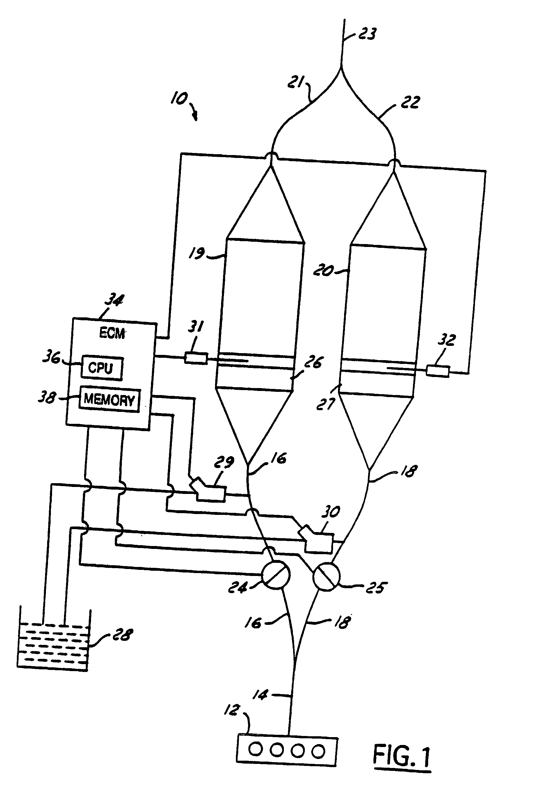
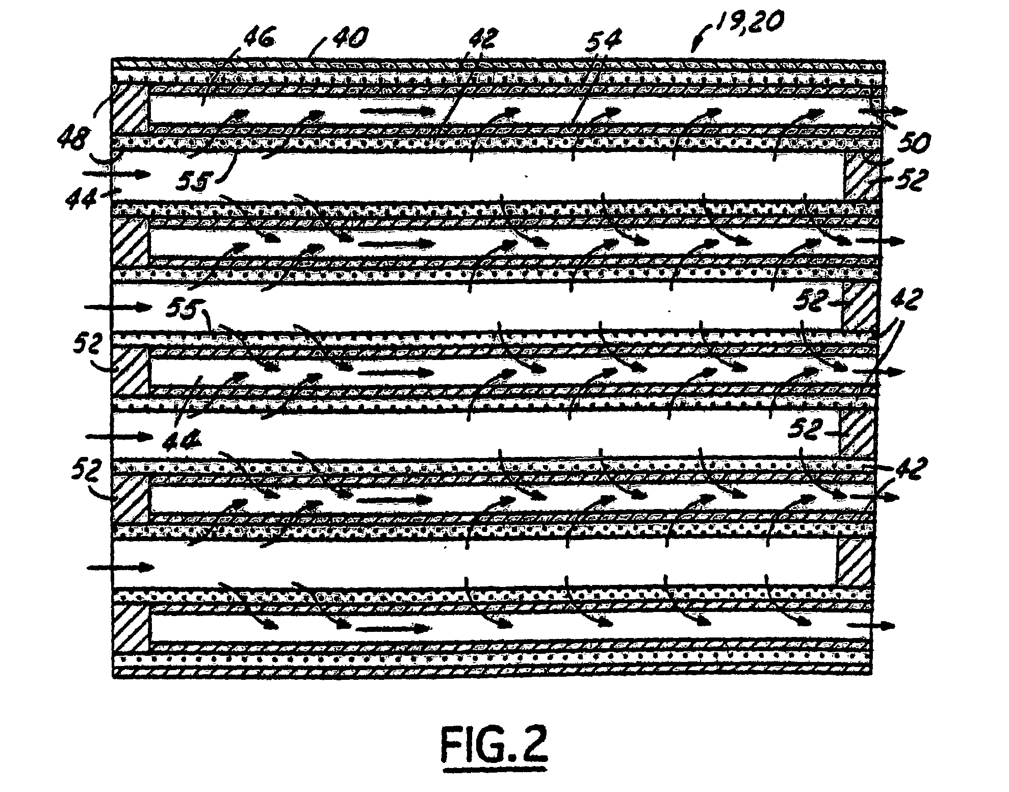
[0014] Referring now to FIG. 1, an exhaust system 10 is illustrated in operational relationship with an internal combustion engine 12 such as a diesel engine for a vehicle such as an automotive vehicle (not shown). The engine 12 has an exhaust manifold 14 to direct the exhaust gases from engine 12 to exhaust system 10. The exhaust manifold 14 is divided into two exhaust intake conduits 16, 18. The exhaust intake conduits 16, 18 direct exhaust gases through two integrated NO.sub.x trap / particulate filters 19, 20. The outputs of the filters 19, 20 are directed through two exhaust output conduits 21, 22 to a muffler or tail pipe 23. The amount of exhaust gases flowing to filters 19, 20 is controlled by control valves 24, 25, respectively. Conventional oxidation catalysts 26, 27 are located upstream and proximate filters 19, 20, respectively.

[0015] The oxidation catalysts 26, 27 serve several functions. First, catalysts 26, 27 are utilized to accurately control temperatures in filters 1...


PUM

PropertyMeasurementUnit
pore sizeaaaaaaaaaa
thicknessaaaaaaaaaa
temperatureaaaaaaaaaa

Abstract

A system and method for removing SOx and particulate matter from an emission control device receiving exhaust gases from an engine is provided. The method includes adding a reductant to the exhaust gases to increase a temperature of the emission control device above a threshold temperature. The method further includes ceasing adding the reductant to the exhaust gases to remove particulate matter from the device. The method further includes adding additional reductant to the exhaust gases to remove SOx from the device.

Description

[0001] The present invention relates to a system and method for removing SOx and particulate matter from an emission control device coupled to an engine.DESCRIPTION OF THE RELATED ART[0002] A known engine control system for purging SOx and particulate matter from a combined particulate filter and NOx trap is disclosed in Japanese Patent 06-272541A. In particular, the control system operates the engine lean while adding reductant to exhaust gases to increase a temperature of the exhaust gases. The increased temperature is used to oxidize particulate matter stored in the combined filter and trap. This process is called particulate filter regeneration. Thereafter, the control system adds more reductant to purge sulphur-oxides (SOx) from the combined filter and trap.[0003] The known control system, however, has a significant drawback. In particular, the control system supplies reductant / fuel to exhaust gases during the purging of particulate matter. As a result, the fuel economy of the ...

Claims


Application Information

Patent Timeline
Patent Type & Authority Applications(United States)
IPC IPC(8): B01D53/94F01N3/023F01N3/035F01N3/08F01N3/20F01N9/00F01N13/02F01N13/04
CPCB01D53/9431F01N13/011F01N3/0231F01N3/035F01N3/0814F01N3/0821F01N3/0842F01N3/085F01N3/0878F01N3/0885F01N9/00F01N2510/06F01N2560/06F01N2560/07F01N2570/04F01N2570/14F01N2610/03F01N2610/146Y02T10/47Y02T10/24F01N13/009B01D53/9495Y02A50/20Y02T10/12Y02T10/40
Inventor HEPBURN, JEFFREY SCOTTHAMMERLE, ROBERT HENRY
Owner FORD GLOBAL TECH LLC
Why Eureka
Try Eureka