Exercise apparatus

Active Publication Date: 2003-06-26
KEISER
View PDF41 Cites 60 Cited by
  • Summary
  • Abstract
  • Description
  • Claims
  • Application Information

AI Technical Summary

Problems solved by technology

Weight stack machines often, in normal use, do not provide a consistent resistance.
If the weight lifter quickly moves the weight, the changes in speed of movement will cause the weight to change.
However, if a user accelerates the weight during the exercise stroke, the resistance force will change.
Such exercise equipment simulat

Method used


Image

  • Exercise apparatus
  • Exercise apparatus
  • Exercise apparatus

Examples


Embodiment Construction

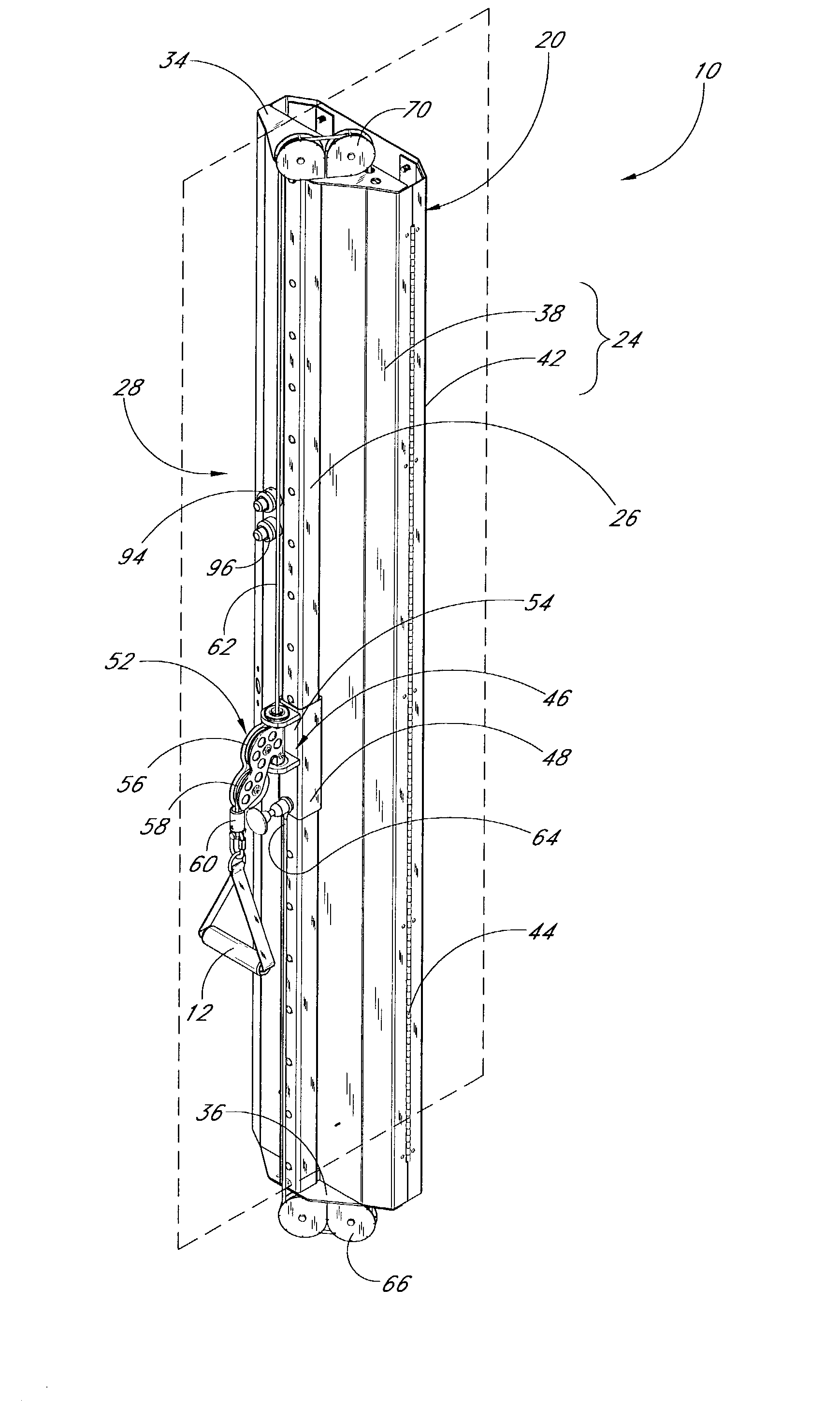
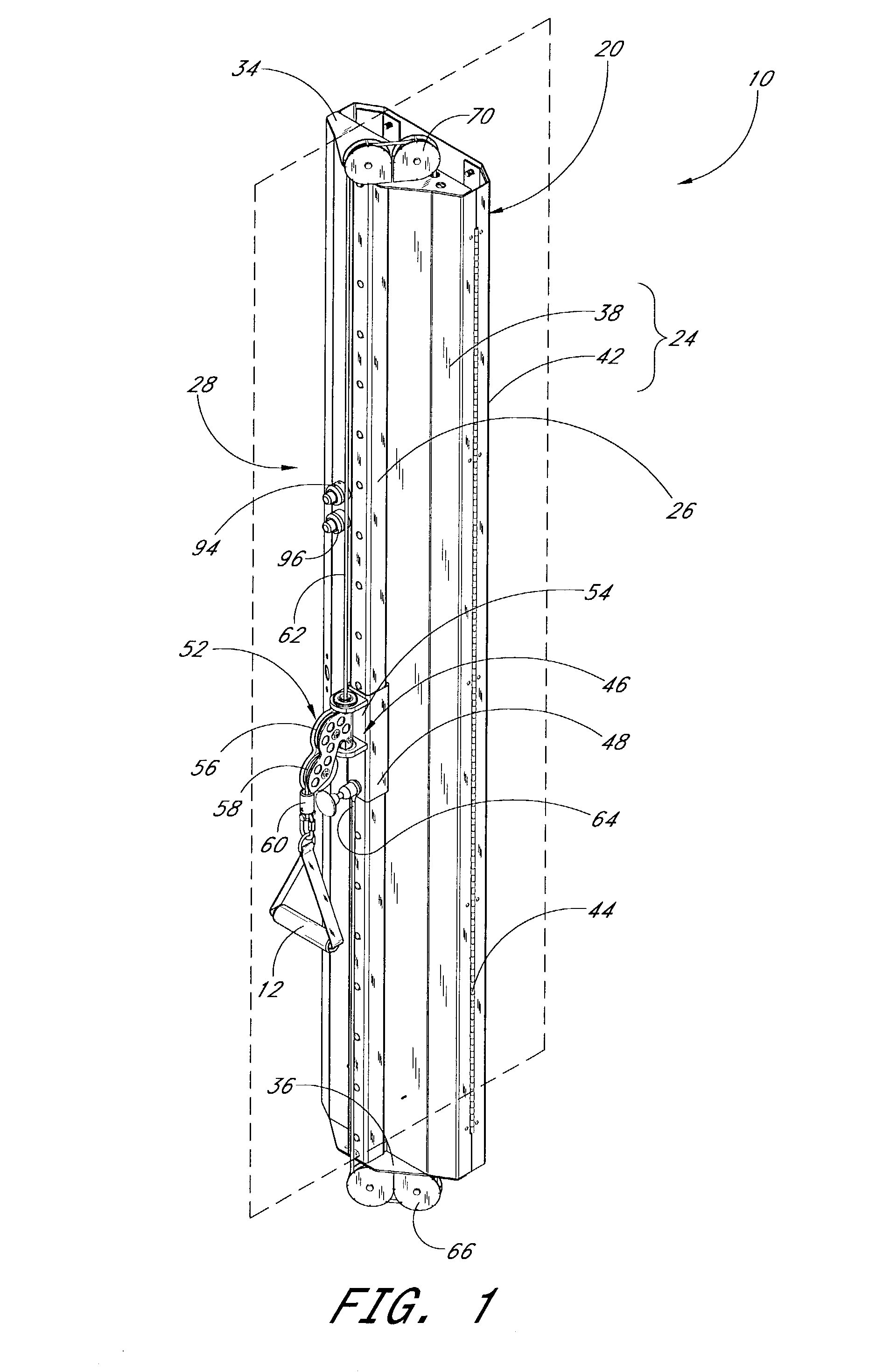
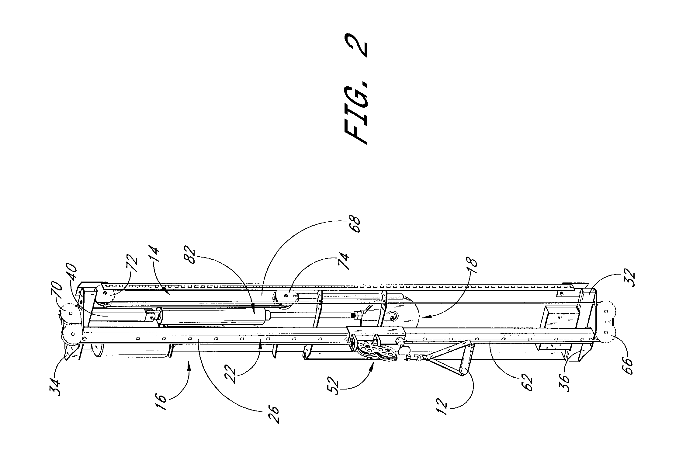
[0038] The present exercise apparatus can take a variety of forms and can be used in a variety of manners as will be apparent from the description of the following embodiments. Additionally, some of the embodiments include a combination of some of the aspects and features described above, and others will include additional aspects and features. As noted above, not all of the aspects and features of the present invention need to be employed in a single embodiment.

[0039] Each illustrated embodiment includes a pneumatic resistance unit that allows for variable resistance and variable degrees and extensions of motion by the user. In addition, the resistance units are designed to permit the user to perform a wide variety of exercises to work various muscles or muscle groups with the same piece of equipment. As will be apparent from the following description of the preferred embodiments, the resistance unit can be stationary or movable, and can include movable pulleys that allow the user ...


PUM


Abstract

An exercise apparatus includes a compact resistance unit that houses a pneumatic cylinder. The cylinder is connected to a pulley wheel that moves at least toward the cylinder. A main cable extends about a portion of the pulley wheel. One end of the main cable is fixed to the unit housing and the other end is attached to a pulley block of a block-and-tackle mechanism. A user cable extends through the block-and-tackle mechanism and is connected to a handle. The pneumatic cylinder resists movement of the handle away from the unit.

Description

[0001] 1. Field of the Invention[0002] The present invention relates to an exercise apparatus and, more particularly, to an adjustable exercise apparatus that can be used for a multitude of exercises.[0003] 2. Description of Related Art[0004] Many exercise devices have been developed of a "weight type" in which weights provide resistance to the exertion of muscular force. Such machines commonly employ weight stacks that allow a user to vary the weight lifted during the exercise. U.S. Pat. Nos. 6,447,430, 5,776,040, and 4,500,089 are examples of such machines.[0005] Weight stack machines often, in normal use, do not provide a consistent resistance. A weight lifter normally thinks that 100 pounds of weight will provide 100 pounds of resistance throughout the exercise stroke; however, this is true only if the weight is moved at a slow and generally constant speed. If the weight lifter quickly moves the weight, the changes in speed of movement will cause the weight to change. Accordingl...

Claims


Application Information

Patent Timeline
IPC IPC(8): A63B21/00A63B21/008A63B22/00A63B23/12
CPCA63B21/0087A63B21/155A63B21/156A63B23/12Y10S482/907A63B2225/30A63B21/1484A63B21/00072A63B21/00069A63B2225/09A63B21/4043A63B23/1209A63B23/03508A63B23/03533A63B23/03541A63B21/4035
Inventor KEISER, DENNIS L.
Owner KEISER
Why Eureka
Try Eureka