
Golf Shoe Cleat

a technology for golf shoes and cleats, which is applied in the field of golf shoe cleats, can solve the problems of damaging the grass, affecting the performance of subsequent players, and affecting the cleaning effect of the clubhouse,

Inactive Publication Date: 2003-07-17
JAPANA CO LTD
View PDF4 Cites 49 Cited by
  • Summary
  • Abstract
  • Description
  • Claims
  • Application Information

AI Technical Summary

Benefits of technology

[0049] An advantage of "forced extraction molding" is that this method sufficiently lowers production costs by reducing the costs for preparing molds because such molds can be simply designed and made easily as will be readily appreciated by persons skilled in the molding art. The molding processes are also simple.

Problems solved by technology

Good grips and bites are provided because relatively long metallic spikes penetrate deep through grass into the ground beneath the grass, which is often damaging to the grass by the roots.
Subsequent players are often troubled by roughened putting greens.
In addition, sharp metallic spikes can damage floor tiles or carpets of clubhouses.
Sharp pushpin type metallic spikes are not very comfortable to walk on, either, especially on hard surfaces such as floors or pavements.
Metallic spikes do not provide stability to wearers due mainly to a limited number of contact points with grounds and hardness of the contact points that contact grounds.
Wearers of spiked shoes may easily lose body balance on hard surfaces particularly when the surfaces are wet or slippery.
Metallic spikes may hurt wearers' feet, knees or waists as the shocks from the physical contacts between the metallic spikes and hard grounds can be directly transmitted to the wearers' feet because metallic spikes do not absorb such shocks.
However, such conventional plastic cleats do not generally provide as good grips or bites on grass or turf as metallic spikes do.
Conventional plastic cleats often fail to provide grips on wet grass, withered grass or slopes.
However, since the legs 32 cannot effectively sustain wearers' weights due to the intrinsic weakness generated from the design features thereof, the legs 32 easily open outwardly as shown in FIG. 14 and lose grips on turf.
Wearers do not necessarily get comfortable feelings on hard surfaces because of the "unique softness" the legs 32 provide as they are deformed.
The cleats 30 do not provide good abrasion resistance, either, and they wear out rapidly.
It is not possible to push a designed material out of a mold having a "narrow" extraction opening after the injected material has completely hardened within the mold.

Method used


Image

  • Golf Shoe Cleat
  • Golf Shoe Cleat
  • Golf Shoe Cleat

Examples


Embodiment Construction

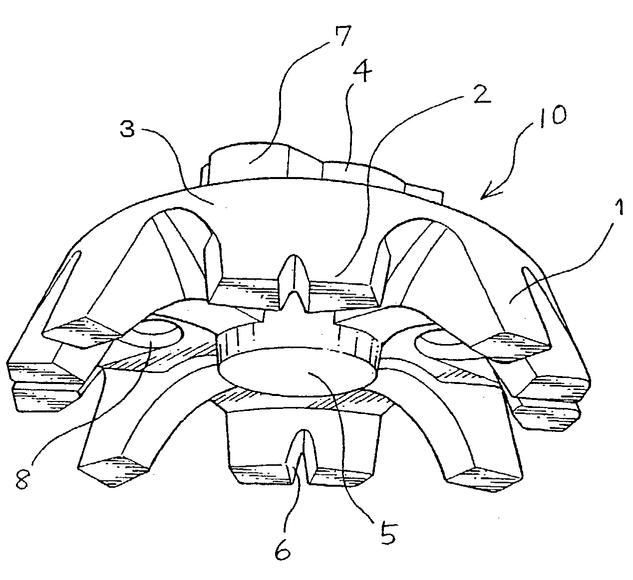
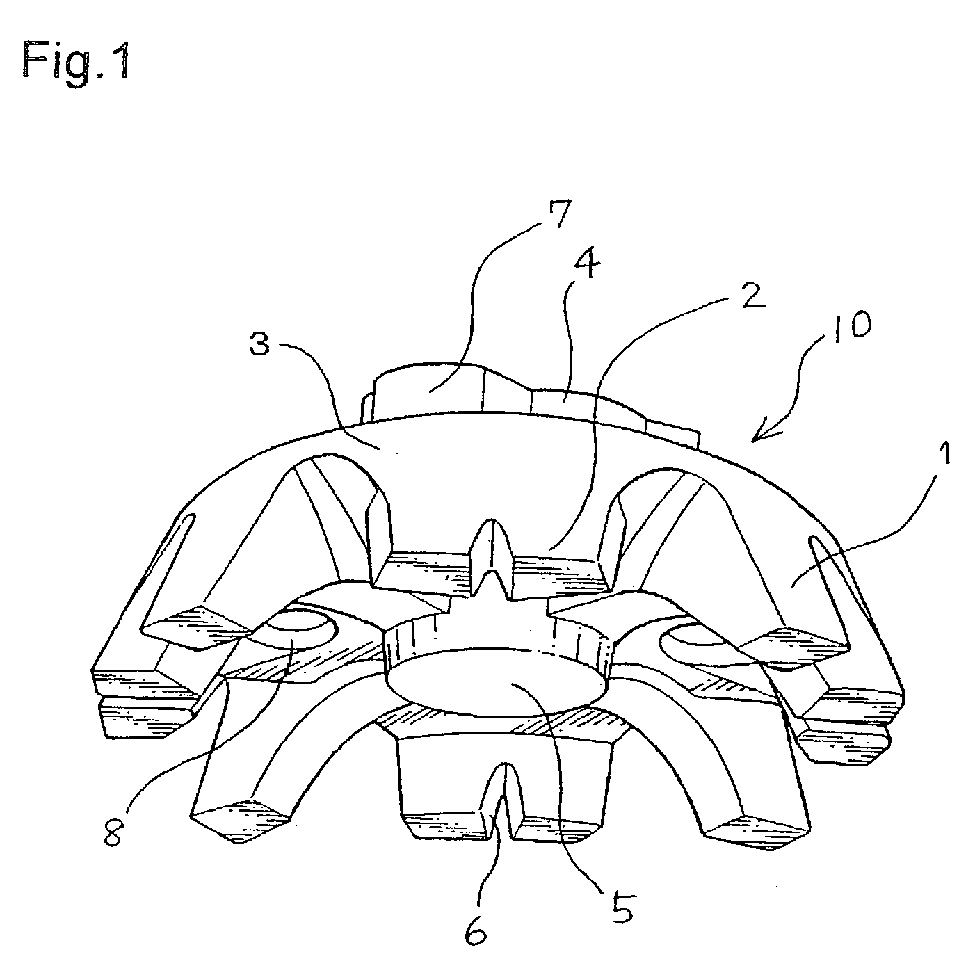
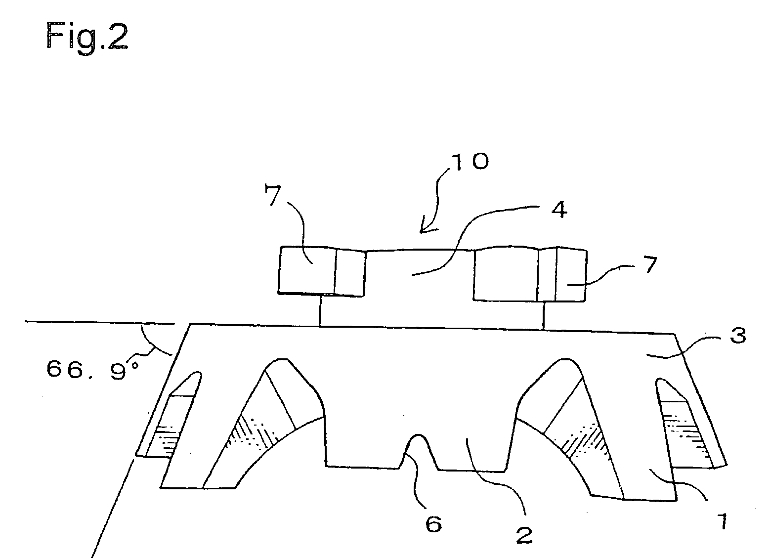
[0069] In FIG. 1 is shown a plastic cleat 10 according to an embodiment (No. 1) of the present invention. The cleat 10 is integrally injection molded with a polyurethane material by "forced extraction molding" of the present invention. The cleat 10 comprises a circular cleat body 3, securing means 4, four flexible protrusions 1 and four rigid protrusions 2. Protrusions 1 and 2 are alternately provided on the periphery of the cleat body 3. The cleat 10 further comprises a circular central protrusion 5 provided on the cleat body 3.

[0070] It is to be noted that it is within the scope of the present invention to provide more flexible protrusions 1 than rigid protrusions 2 on a cleat body 3 and arrange them "alternately" on the cleat body 3 meaning more than one flexible protrusions 1 can be arranged between any two rigid protrusions, or less flexible protrusions than rigid protrusions 2 and arrange them "alternately", meaning at least one pair of adjacent rigid protrusions 2 do not flan...


PUM


Abstract

A plastic cleat (10) for a golf shoe is disclosed, including a cleat body (3), a plurality of flexible protrusions (1) and rigid protrusions (2) extending from the cleat body (3). The flexible protrusions (1) and rigid protrusions (2) provide good grips on grass without damaging the grass. The flexible protrusions (1) bend outwardly on a hard surface, when the rigid protrusions (2) chiefly support weight. The cleat (10) can be economically manufactured by "forced extraction molding" utilizing the shape rebounding nature of half hardened plastic materials.

Description

[0001] 1Field of the Invention[0002] This invention generally relates to a cleat. More particularly, this invention relates to a cleat to be used on golf shoes. This invention also relates to a method for manufacturing plastic golf shoe cleats.[0003] 2. Related Art[0004] Pushpin type metallic spikes or cleats are conventionally used on golf shoes. Some are integrally provided and some are detachably provided on golf shoe soles. Such metallic spikes generally provide satisfactory grips or bites on grass or turf on the golf courses even when the grass or turf is wet.[0005] Good grips and bites are provided because relatively long metallic spikes penetrate deep through grass into the ground beneath the grass, which is often damaging to the grass by the roots. The golfing ground will also get considerably roughened by metallic spikes. This problem is multiplied on putting greens. Subsequent players are often troubled by roughened putting greens. In addition, sharp metallic spikes can da...

Claims


Application Information

Patent Timeline
IPC IPC(8): A43B5/00A43C15/02A43B13/26A43C15/16B29D35/12
CPCA43B5/001B29D35/12A43C15/162
Inventor TERASHIMA, YASUYUKI
Owner JAPANA CO LTD
Learn More