Structure of an adjustable LCD screen

a technology of lcd screen and structure, which is applied in the direction of television system, electrical apparatus casing/cabinet/drawer, instruments, etc., can solve the problems of lcd screen not being rotatable after an extended period of time, requiring a large amount of force to rotate or adjust the angle of lcd screen,

Inactive Publication Date: 2003-07-17
WU ALPHA
View PDF6 Cites 54 Cited by
  • Summary
  • Abstract
  • Description
  • Claims
  • Application Information

AI Technical Summary

Problems solved by technology

However, due to the entire weight of the LCD is exerted onto the bottom seat, a great force is required in order to rotate or adjust the angle of the LCD screen.
In addition, the dust collected on the bottom seat will further deter the rotating of the LCD screen.
As a result, the LCD screen may not be rotatable after an extended period of time.

Method used


Image

  • Structure of an adjustable LCD screen
  • Structure of an adjustable LCD screen
  • Structure of an adjustable LCD screen

Examples


Embodiment Construction

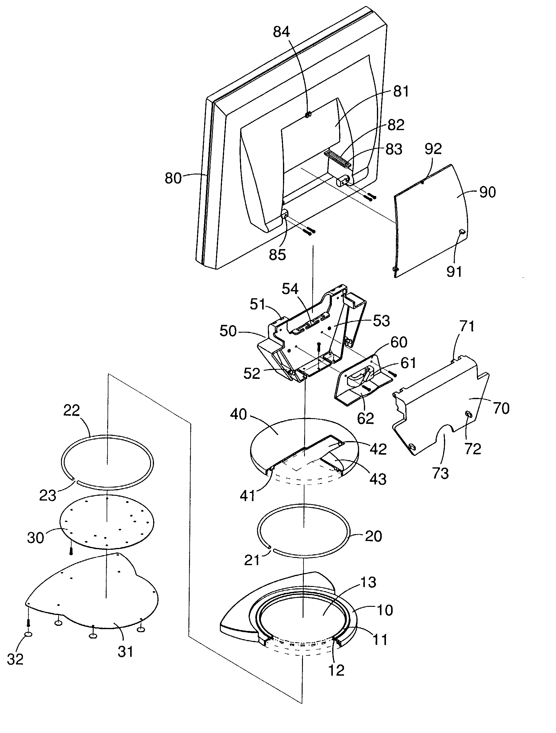
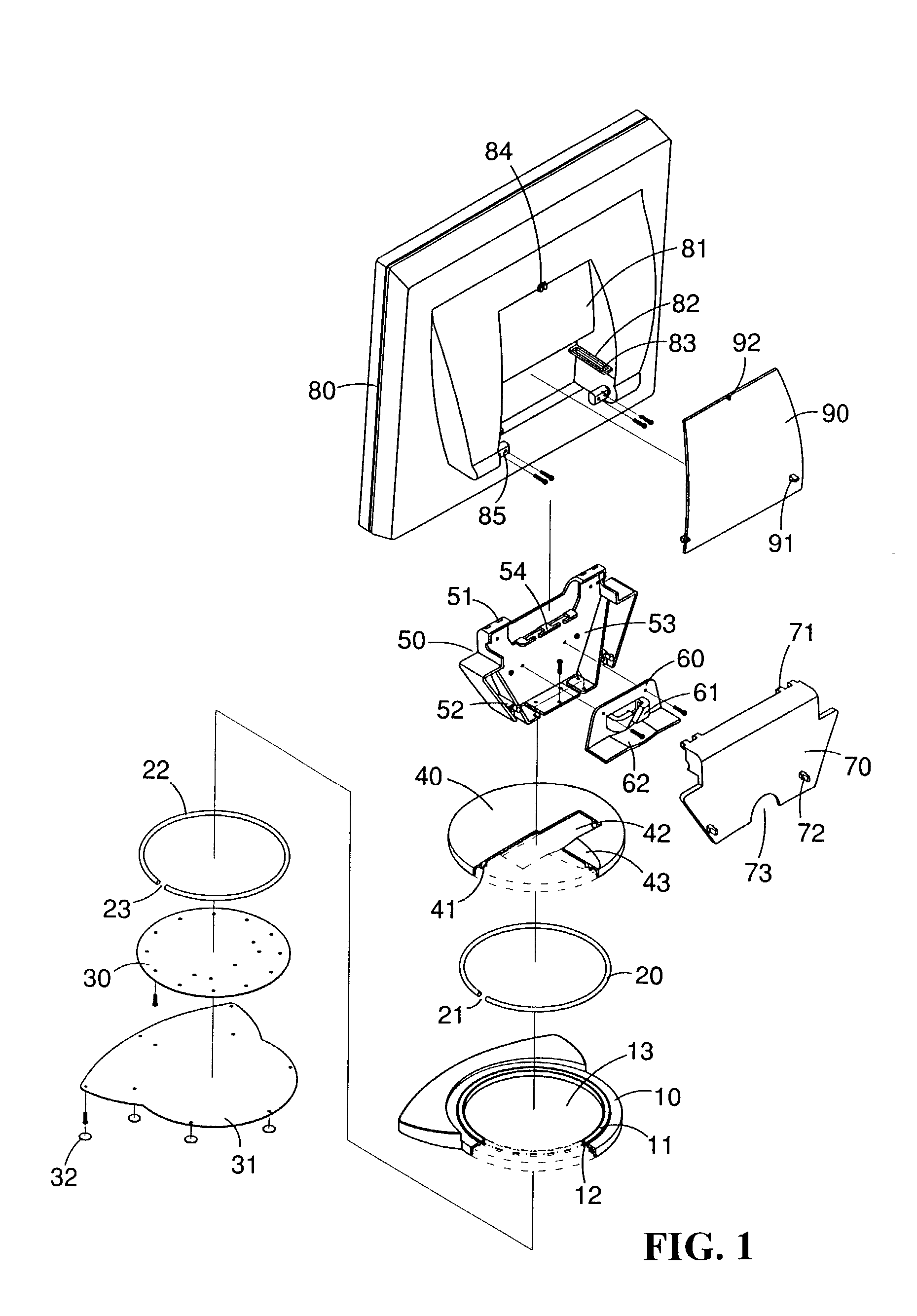
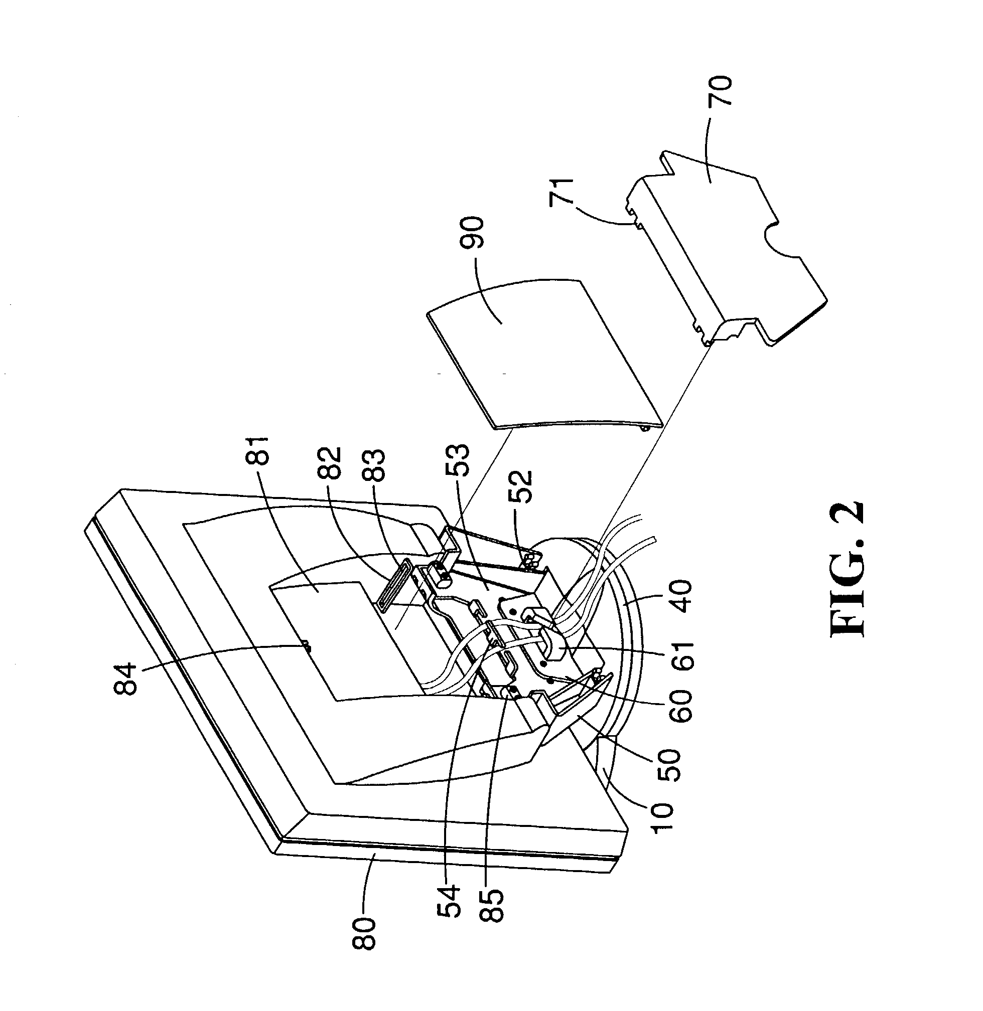
[0014] Referring to FIGS. 1 to 4, there is shown an improved structure of an adjustable LCD screen comprising

[0015] (a) a base seat 10 having a top and a bottom side respectively mounted with a top groove 11 and a bottom groove 12 of co-axial, and the inner side of the base seat 10 of the top groove 11 and the bottom groove 12 being provided with a circular hole 13;

[0016] (b) a top ring 20 having a lower section being engaged with the top groove 11 and the top ring 20 being made from a wear-resistant and of low coefficient of friction material, a notch 21 being provided to the top ring 20 facilitating the engagement with the top groove 11;

[0017] (c) a bottom ring 22 having a upper section being engaged with the bottom groove 12 and the bottom ring 22 being made from a wear-resistant and of low coefficient of friction material, and a notch 23 being provided tot he bottom ring 22 facilitating the engagement with the bottom groove 12;

[0018] (d) a base plate 30 mounted at the bottom sec...


PUM


Abstract

An improved structure of an adjustable LCD screen is disclosed. The LCD screen can be adjusted in 360 degree and the inclination angle of the LCD can also be adjusted. The LCD screen comprises (a) a base seat having a top and a bottom side respectively mounted with a top groove and a bottom groove of co-axial, and the inner side and the base seat at the top groove being provided with a circular hole; (b) a top ring having a lower section being engaged with the top groove and the top ring being made from a wear-resistant and low coefficient of friction material; (c) a bottom ring having a upper section being engaged with the bottom groove and the bottom ring being made from a wear-resistant and low coefficient of friction material; (d) a base plate mounted at the bottom section of the base seat and the bottom ring being urged at the bottom groove; (e) a base seat plate covered the bottom section of the base seat for sealing the bottom face thereof; (f) a rotating disc having a disc groove matching with the top groove at the bottom section allowing the top section of the top ring engaged thereto, and an engaging groove being provided on the rotating disc; (g) a supporting seat having a fixed board engaged with the engaging groove and being secured at the base plate; (h) a string seat fixed to the fixed board and the engaging groove being covered, and the string seat being provided with a string hook; (i) a supporting seat cover mounted to the rear side of the supporting seat and the bottom section thereof being a notch; (j) a screen having a rear side provided with a cavity which has two sides rotatably mounted with a positioning pivotal rod, the rod being provided with one end mounted onto the fixed board; and (k) a screen rear cover mounted onto the cavity.

Description

[0001] (A) Technical Field[0002] The present invention relates to structure of a LCD screen, and in particular, a LCD screen which is adjustable in an axial direction and in inclination angle.[0003] (B) Brief Description of the Prior Art[0004] Taiwanese Patent Publication No. 351151, 351510, and 410988 disclose a LCD screen having a holding seat positioned at the bottom seat thereof. A protruded edge at the holding seat engages with a sliding groove of the bottom seat such that the holding seat can rotate an appropriate angle on the bottom seat. However, due to the entire weight of the LCD is exerted onto the bottom seat, a great force is required in order to rotate or adjust the angle of the LCD screen. In addition, the dust collected on the bottom seat will further deter the rotating of the LCD screen. As a result, the LCD screen may not be rotatable after an extended period of time. Accordingly it is an object of the present invention to provide an improved structure of a LCD scr...

Claims


Application Information

Patent Timeline
Patent Type & Authority Applications(United States)
IPC IPC(8): F16M11/08F16M11/10F16M11/12
CPCF16M11/08F16M11/10Y10S248/919F16M11/2014F16M2200/08F16M11/12
Inventor JU, LI TA
Owner WU ALPHA
Why Eureka
Try Eureka