Roller bearing in a deep-drilling apparatus

a technology of roller bearings and deep drilling, which is applied in the direction of sliding contact bearings, mechanical equipment, rotary machine parts, etc., can solve the problems of large reduction of the service life rapid wear of the roller bearing, and water penetration into the roller bearing. , to achieve the effect of prolonging the service li

Inactive Publication Date: 2003-07-24
SCHAEFFLER KG
View PDF4 Cites 14 Cited by
  • Summary
  • Abstract
  • Description
  • Claims
  • Application Information

AI Technical Summary

Benefits of technology

[0005] It is therefore an object of the present invention to provide a roller bearing for a deep-drilling apparatuses which has a longer service life under operating conditions in which drilling water runs through the bearing.

Problems solved by technology

One effect is rapid wear of the roller bearings.
The problem with these seals is that the water can penetrate into the roller bearing despite the seals.
Then the impurities in the water damage the roller bearing, so that the service life of the roller bearing is greatly reduced.
But an even longer service life of the roller bearing would be desirable, because changing the roller bearing is very expensive for the operator of the deep-drilling apparatus.

Method used


Image

  • Roller bearing in a deep-drilling apparatus
  • Roller bearing in a deep-drilling apparatus
  • Roller bearing in a deep-drilling apparatus

Examples


Embodiment Construction

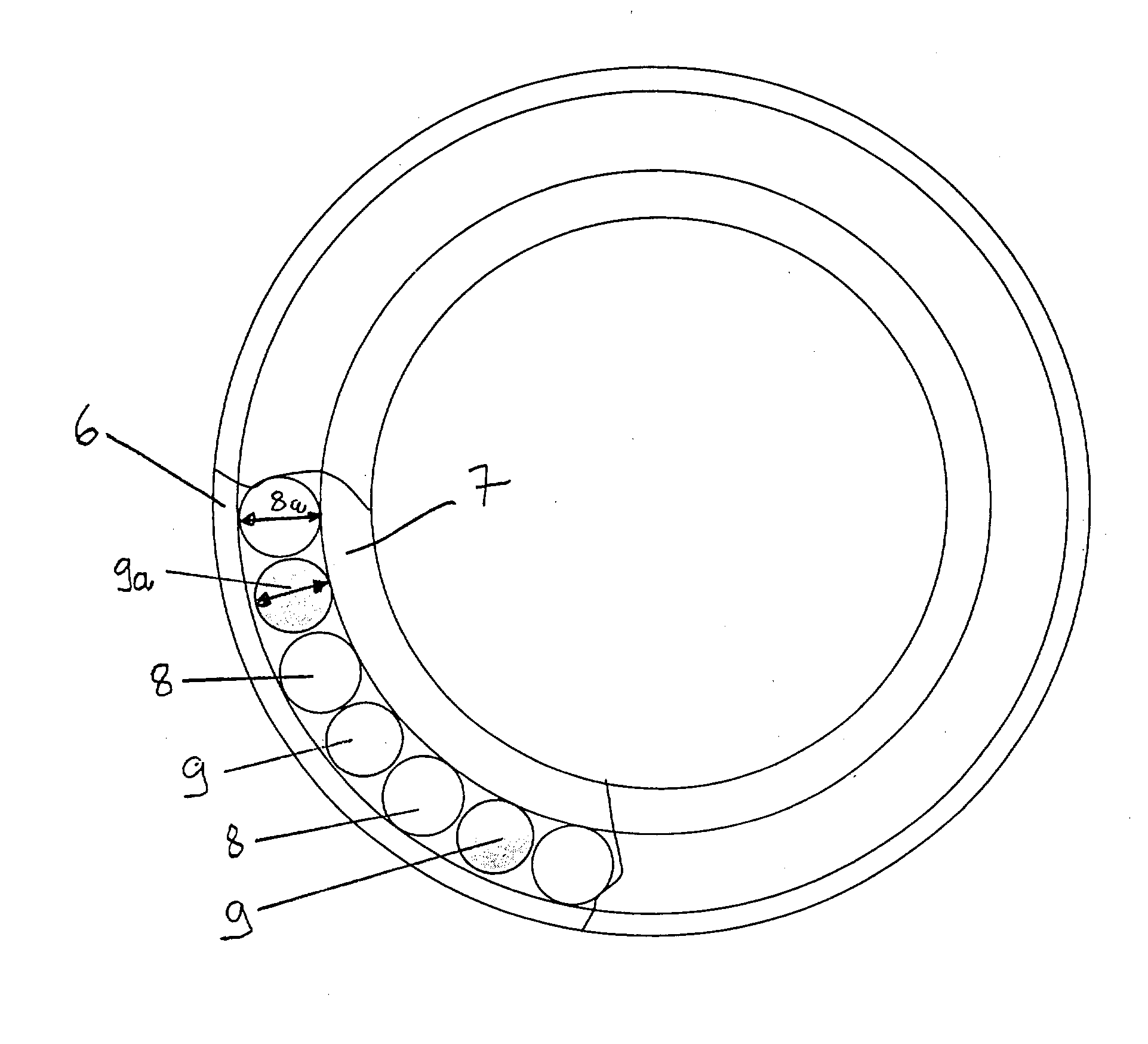
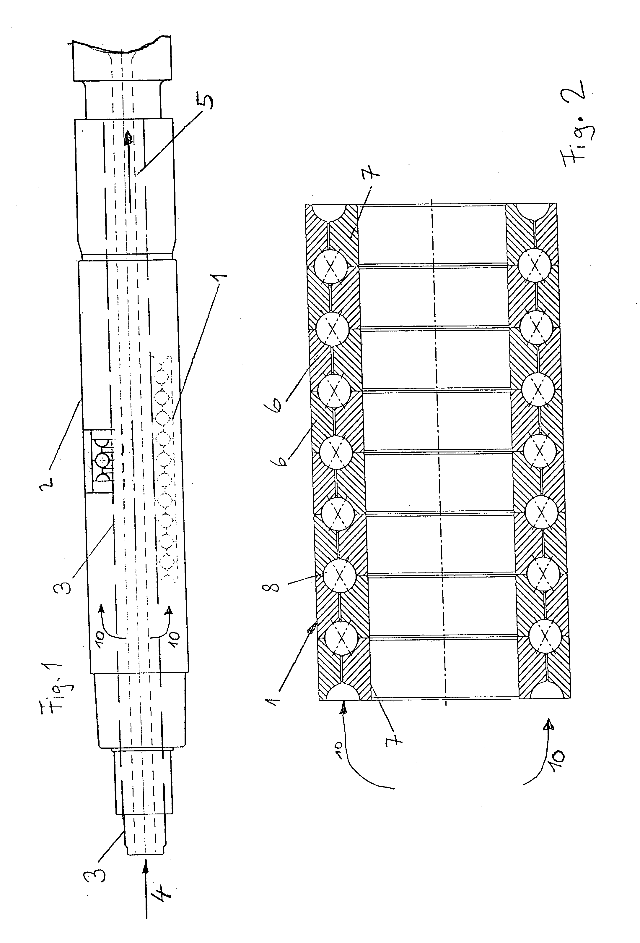
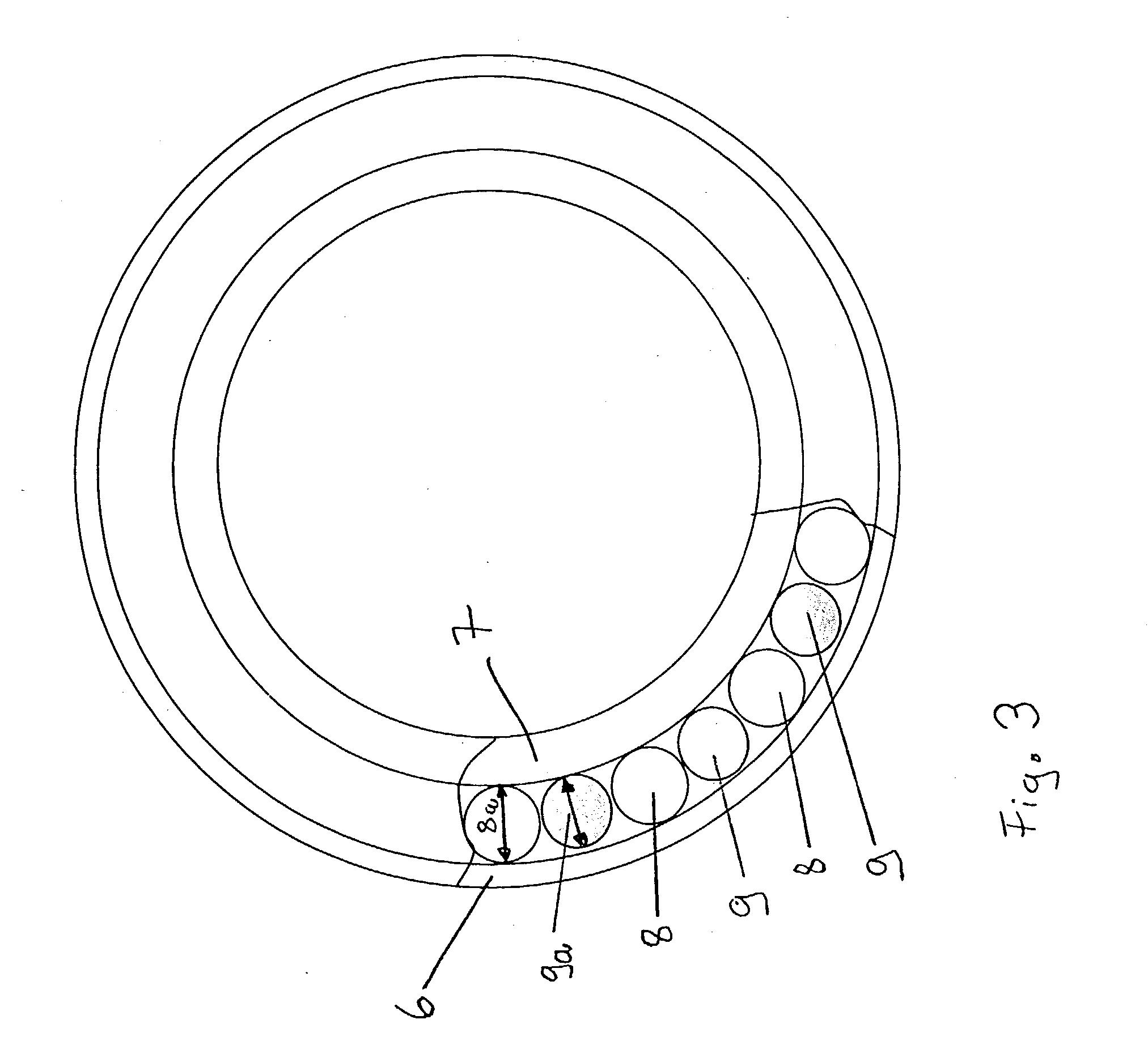
[0007] In the invention which concern a ball bearing load-bearing balls are made from ceramic and are spaced a distance apart from each other by slightly smaller separating balls made from steel or an appropriate other metal or material which serves the separating function described herein. The bearing tracks of the bearing races are likewise made from steel or such other material. As a result, the load-bearing roller bodies made only from ceramic make rolling contact with steel surfaces or the other material surfaces.

[0008] In the case there are impurities, e.g., from drilling, in the roller bearing, and in the case of defective lubrication, direct material contact takes place during rolling. In the invention, this direct material contact is always between ceramic and the steel or the other material. It has been found, surprisingly, that in the event of defective lubrication, the wear between bodies in rolling contact (steel and ceramic) is less than in the case of prior art rollin...


PUM


Abstract

A ball-bearing unit for a bearing of a deep-drilling apparatus having bearing races made from steel with balls disposed therebetween. Contaminated drilling medium passes into the space between the bearing races. Load-bearing balls made from ceramic alternate with separating balls of smaller diameter made from steel between the bearing races to extend significantly the service life of the ball-bearing unit.

Description

[0001] The invention relates to the mounting of a hollow shaft between a drilling head and drive turbine in a deep-drilling apparatus.[0002] In deep-drilling rigs, drilling heads that are driven in the well have long been in use. Drilling liquid is pumped through a stationary pipe under pressure from outside toward the drilling head. A turbine at the end of the pipe converts the pressure of the drilling liquid into a rotary movement that drives the drilling head. After it has passed the turbine, the drilling liquid runs through a hollow shaft to the drilling head to lubricate and cool the drilling head. Drilling liquid, flows back to the surface outside the drilling head and carries drilled-out rock to the surface. Because of the rough ambient conditions, the drilling liquid, containing impurities, repeatedly penetrates into the roller bearings. One effect is rapid wear of the roller bearings.[0003] The roller bearing used in the drilling head in DE 25 27 237 C3 is protected by spec...

Claims


Application Information

Patent Timeline
Patent Type & Authority Applications(United States)
IPC IPC(8): F03D11/00F16C19/20F16C33/32F16C33/37
CPCF16C19/20F16C33/32F16C2206/40F16C2352/00F16C33/3713F16C19/181F16C2240/70
Inventor HERLES, GUNTERGOBEL, DIETERMUTZEL, RICHARD
Owner SCHAEFFLER KG
Why Eureka
Try Eureka