Adjustable long bone prosthesis

Inactive Publication Date: 2003-07-24
DEPUY SYNTHES PROD INC +1
View PDF2 Cites 45 Cited by
  • Summary
  • Abstract
  • Description
  • Claims
  • Application Information

AI Technical Summary

Benefits of technology

0009] In order to address these needs, the present invention contemplates an adjustable long bone prosthesis that can be readily adjusted within the patient to account for discrepancies in the measurement of a long bone to be replaced. The inventive prosthesis includes a first elongated component having a first end configured to engage a first prosthetic joint, such as an elbow joint, and an opposite end having a first

Problems solved by technology

While many devices exists for the replacement of a damaged or defective joint, the substitution of a bone, and particularly a long bone, is much more problematic.
While prosthetic phalanges have enjoyed increasing success, the long bones have not been so easily replaced by a prosthesis, particularly to maintain the functionality of the patient's limb.
Perhaps the greatest difficulty is the extreme load-bearing nature of the long bones.
A further problem associated with a long bone prosthesis is the variability in length of a particular long bone between patients.
One problem common to all of these prior adjustable length features is that the length of the prosthesis cannot be adjusted in situ.
However, in some cases no matter how accurate the x-ray and resulting measurements, certain errors creep in that make accurate measurement of the length of the long bone difficult.
For instance, it is often particularly difficult to obtain an accurat

Method used


Image

  • Adjustable long bone prosthesis
  • Adjustable long bone prosthesis
  • Adjustable long bone prosthesis

Examples


Embodiment Construction

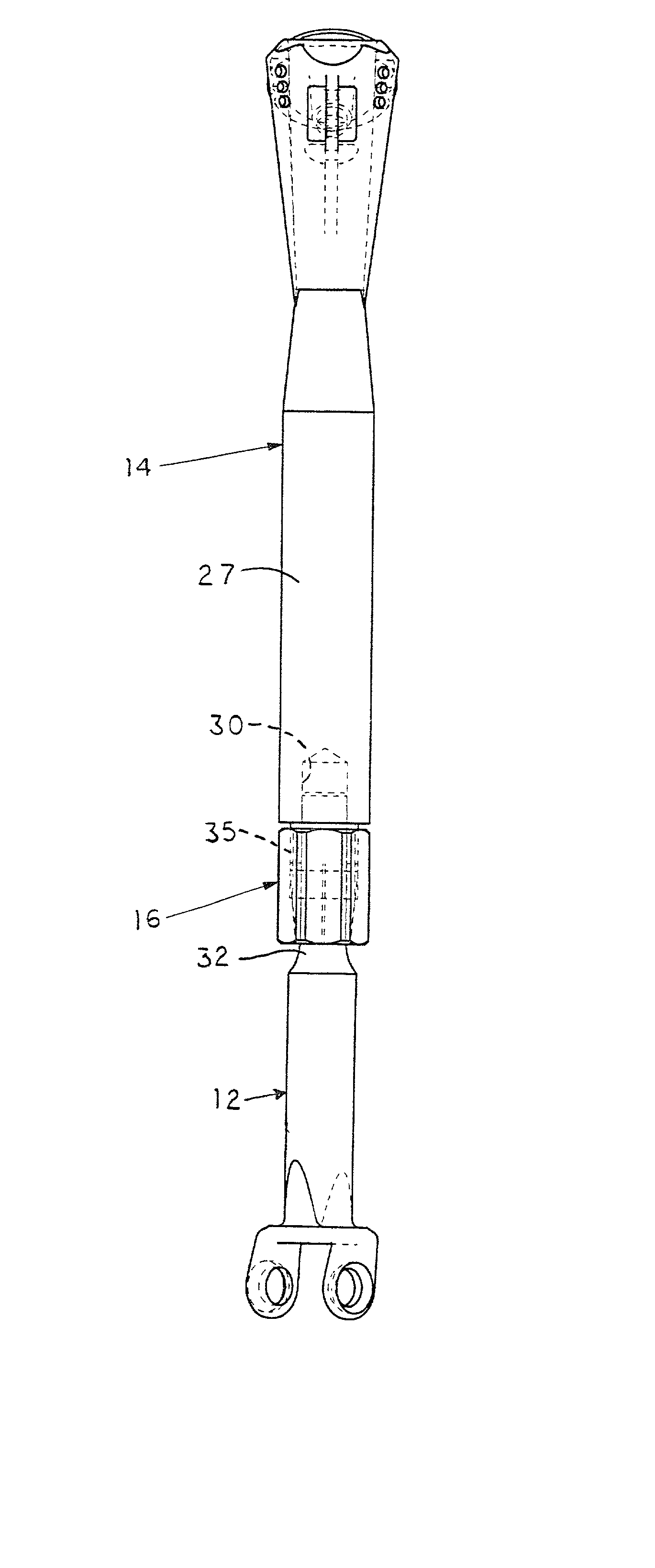
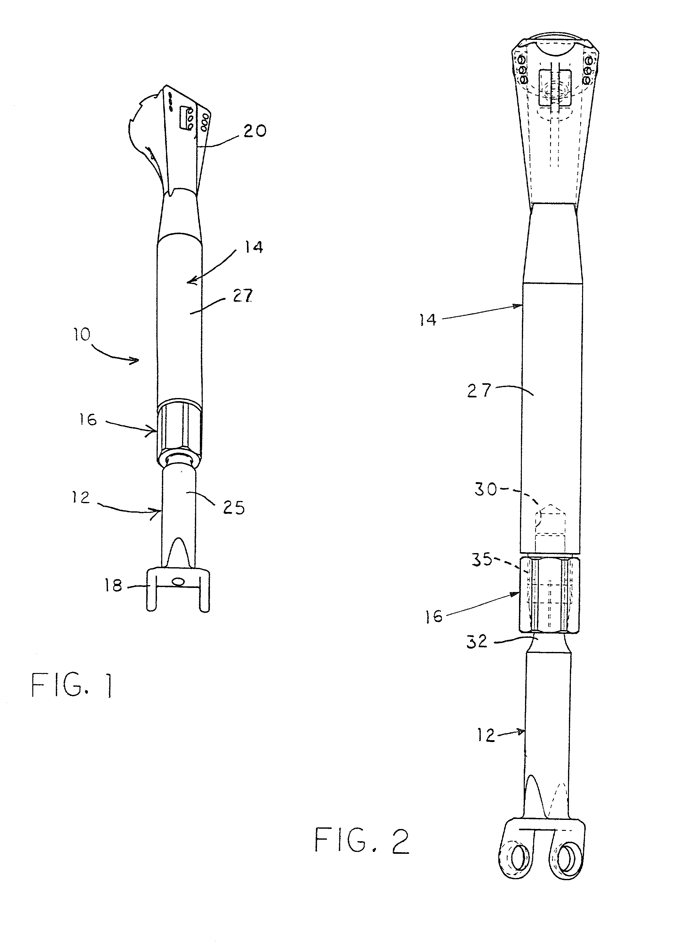
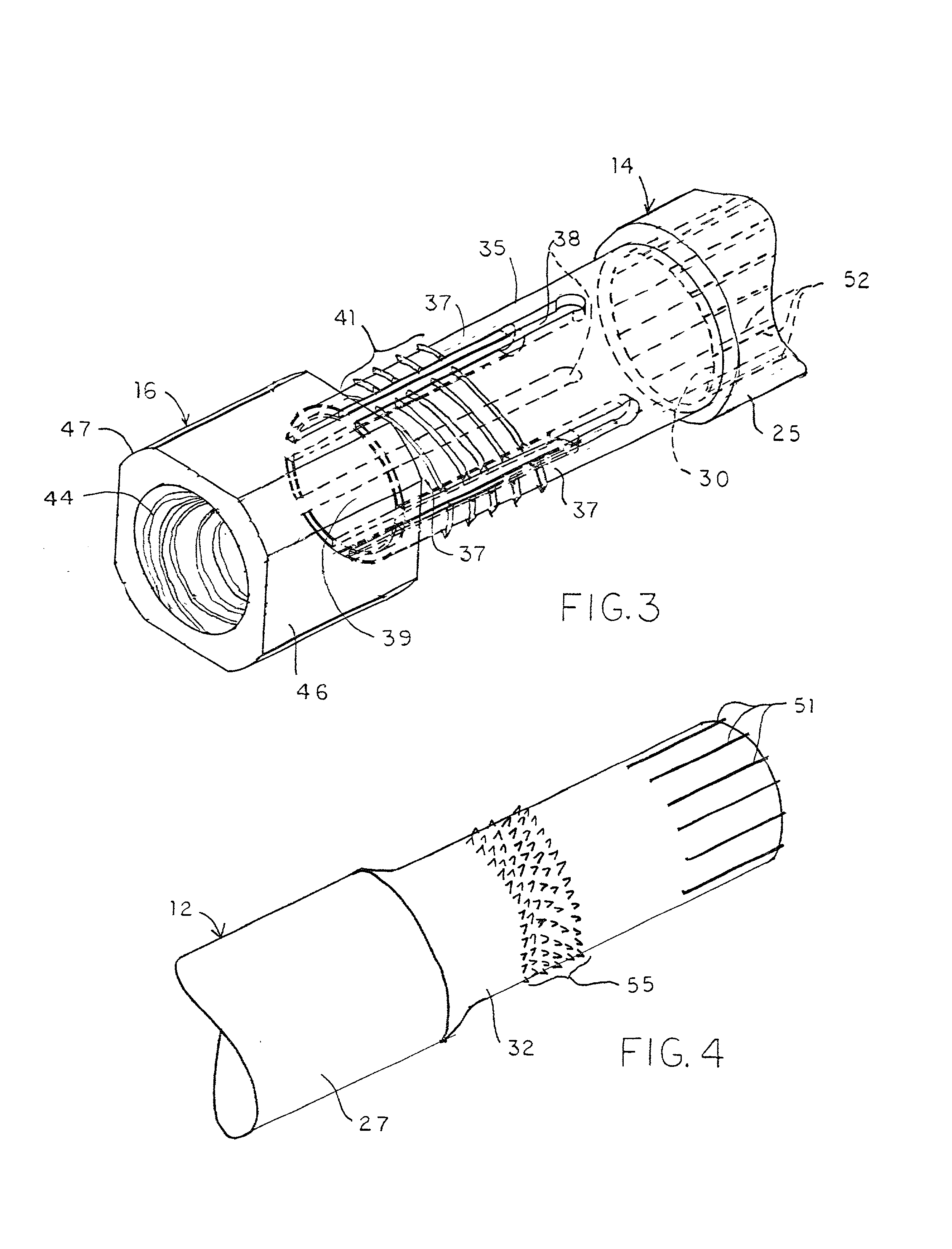
[0021] For the purposes of promoting an understanding of the principles of the invention, reference will now be made to the embodiments illustrated in the drawings and described in the following written specification. It is understood that no limitation to the scope of the invention is thereby intended. It is further understood that the present invention includes any alterations and modifications to the illustrated embodiments and includes further applications of the principles of the invention as would normally occur to one skilled in the art to which this invention pertains.

[0022] The present invention contemplates an adjustable prosthesis that permits adjustment of the length of the prosthesis in situ most preferably, the invention has application for the replacement or substitution of a long bone of a patient, such as the humerus bone. However, the adjustability features of the present invention can be implemented for other prosthesis, such as prosthetic joints. In one aspect of...


PUM


Abstract

A long bone prosthesis includes upper and lower articulating components, with the free ends of the components configured to engage a corresponding prosthetic joint. The overall length of the articulating components is adjustable to approximate the length of a patient's long bone, such as the humerus. The articulating components include a stem and collet arrangement for fixing the relative axial and rotational position of the components. A tapered lock nut is threaded onto the outer threaded surface of the collet portion to provide a pressure engagement of the articulating elements. Various surface features can be implemented among the components of the prosthesis to enhance the pressure fixation, restrict rotation or provide indexed movement of the articulating components relative to each other.

Description

BACKGROUND OF INVENTION[0001] The present invention relates to an orthopedic prosthesis. More specifically, the invention concerns a prosthesis for restoring the functionality of an extremity, such as an arm of a patient. The invention is particularly suited for the replacement of a long bone of the patient.[0002] The later half of the 20.sup.th century has seen a proliferation in the number of human skeletal components that can be replaced by a man-made prosthesis. Over the years these prosthesis have evolved from simply a physical substitution for a bone or a joint, to the more sophisticated fully functional prosthesis. For example, prostheses are well known for the replacement of the shoulder joint or the elbow joint. A modular shoulder prosthesis designed according to U.S. Pat. No. 5,314,479, assigned to DePuy, Inc., can be integrated into the existing glenoid cavity of a patient's shoulder. The prosthesis includes a lower stem that is configured to be embedded within the existi...

Claims


Application Information

Patent Timeline
IPC IPC(8): A61F2/00A61F2/28A61F2/30A61F2/38A61F2/40A61F2/42A61F2/46
CPCA61F2/28A61F2310/00023A61F2/3804A61F2/4059A61F2/4637A61F2002/2825A61F2002/2853A61F2002/2871A61F2002/2892A61F2002/2896A61F2002/3008A61F2002/30154A61F2002/30332A61F2002/30354A61F2002/30355A61F2002/30367A61F2002/30373A61F2002/30377A61F2002/30403A61F2002/30408A61F2002/30448A61F2002/30484A61F2002/30485A61F2002/30512A61F2002/3054A61F2002/3055A61F2002/30551A61F2002/30596A61F2002/30598A61F2002/30601A61F2002/30604A61F2002/30785A61F2002/30787A61F2002/30795A61F2002/30836A61F2002/30881A61F2002/30886A61F2002/30894A61F2002/3822A61F2002/4011A61F2002/4018A61F2002/421A61F2002/4638A61F2002/481A61F2220/0025A61F2220/0033A61F2220/005A61F2230/0021A61F2250/0098A61F2/30942A61F2002/30507A61F2002/30594A61F2/481
Inventor ROGERS, JAMES R.RHOADES, JOEL C.MARTIN, TROY D.
Owner DEPUY SYNTHES PROD INC
Why Eureka
Try Eureka