Communication apparatus

a technology of communication apparatus and communication line, which is applied in the direction of signal generators with optical-mechanical scanning, television systems, data switching networks, etc., can solve the problems of high bandwidth, low bandwidth, and busy telephone lines for the whole duration of the connection

Inactive Publication Date: 2003-08-14
MACAB
View PDF34 Cites 92 Cited by
  • Summary
  • Abstract
  • Description
  • Claims
  • Application Information

AI Technical Summary

Benefits of technology

[0026] It is an object of the present invention to provide a method and an apparatus for connecting end users to a data network, especially the Internet, when the subscribers are connected in a cascade configuration. The apparatus should be inexpensive and easy to maintain.
[0028] With the solution according to the invention, a direct connection of the data signal through the flats in which no data connection is desired is enabled, thus reducing the attenuation in the cascade. Also, it enables the implementation of the communication unit in two parts: one wall mounted part and one adapter connectable to the wall mounted part. The adapter then comprises the connection unit, which is needed only for subscribers who want to have a data connection. Therefore, subscribers who only want the CATV connection do not have to pay for the connection unit, which is the most expensive component.
[0033] This embodiment enables the automatic connection and disconnection of the data connection to the flat, without interrupting the cascade in a flat in which the data connection is disconnected. Also, a more economic construction is achieved, since the Ethernet switch can be placed in a separate, plug-in unit, which only those who really want a data connection need to have.

Problems solved by technology

This solution has two severe drawbacks: the telephone line is busy for the whole duration of the connection and the bandwidth is very low.
CATV modems are relatively expensive.
For residential access the wiring cost may be prohibitively high.
Also, where the signal is branched to a subscriber, the transceiver must be connected very close to the branching point, which represents a problem.

Method used


Image

  • Communication apparatus
  • Communication apparatus
  • Communication apparatus

Examples


Embodiment Construction

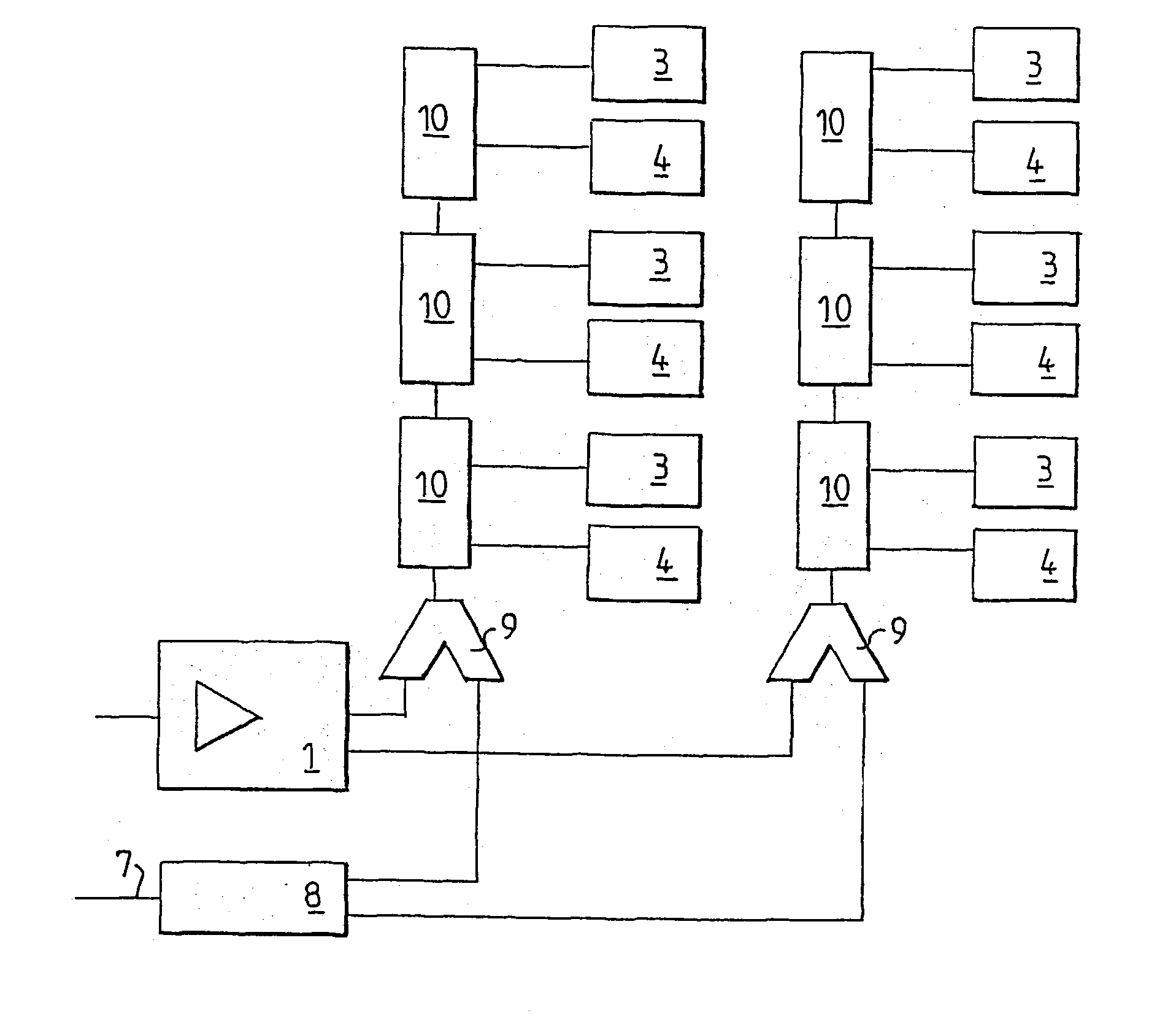
[0043] FIG. 1 shows a preferred embodiment of the invention applied to a cascade coupled network like the one shown in FIG. 1B. A CATV amplifier 1 is used for receiving the TV signal from the CATV network. From the amplifier 1 the TV signal is distributed to a number of flats, each having a television set 3 and a personal computer 4.

[0044] In this embodiment, a separate data network 7 is used for the data communication outside the house. The incoming data from the data network 7 is distributed, in a distribution device 8, to each flat by the in-house CATV network. The distributing device 8 may be a hub which simply distributes the same signal on a number of outputs, or a switch, which switches the incoming data so that only the data intended for the subscribers connected to a particular cascade is transmitted on this cascade. In FIG. 1, two cascades are shown. Only one, or an arbitrary number maybe used.

[0045] To enable the distribution of data signals through the CATV network, a co...


PUM


Abstract

A communication unit comprised a first and second splitting / combining device, each having terminals for receiving and transmitting a CATV signal and a data signal, respectively, means for combining the CATV signal and the data signal and a third terminal for receiving and transmitting the combined signal. The first terminals of the splitting / combining devices are interconnected through a device for extracting said CATV signals and each of the second terminals is connected to a switch controlled in such a way that the second terminals are either connected to each other directly or connected to a connection device for connection to a computer. The data signal can bypass flats desiring no data connection. Also, the communication unit may be implemented in two parts: one wall mounted part and one adapter connectable to the wall mounted part and comprising the connection unit, which is needed only where a data connection is wanted.

Description

[0001] The present invention relates to data network access and in particular to providing access to a data network at relatively low cost, in particular at home.DESCRIPTION OF RELATED ART[0002] There is an increasing requirement for Internet connections from people's homes, both to enable working at home and for private use. A common solution is using modems and the ordinary telephone lines. This solution has two severe drawbacks: the telephone line is busy for the whole duration of the connection and the bandwidth is very low.[0003] It is known in the art to use a cable-TV (CATV) network for the connection from a building to the external data network TV signals and data, for example according to the Ethernet protocol, can share a transmission medium, since the TV signals and the data signals are transmitted on different frequencies and can therefore easily be separated. Each subscriber then has a CATV modem, which extracts the data signal and forwards it to the subscriber's comput...

Claims


Application Information

Patent Timeline
Patent Type & Authority Applications(United States)
IPC IPC(8): H04L12/28H04L12/931
CPCH04L12/2801H04L49/351H04L12/2898
Inventor SAHLIN, DANSODEROVIST, RICKARDHAMMAR, AXEL
Owner MACAB
Why Eureka
Try Eureka