
Database Switch enabling a database area network

a database and switch technology, applied in the field of database, can solve the problems of high cost, complex management, and limited scalability, and achieve the effects of reducing the number of switches, and increasing the number of data centers

Inactive Publication Date: 2003-08-14
DAR SHAUL +3
View PDF7 Cites 146 Cited by
  • Summary
  • Abstract
  • Description
  • Claims
  • Application Information

AI Technical Summary

Problems solved by technology

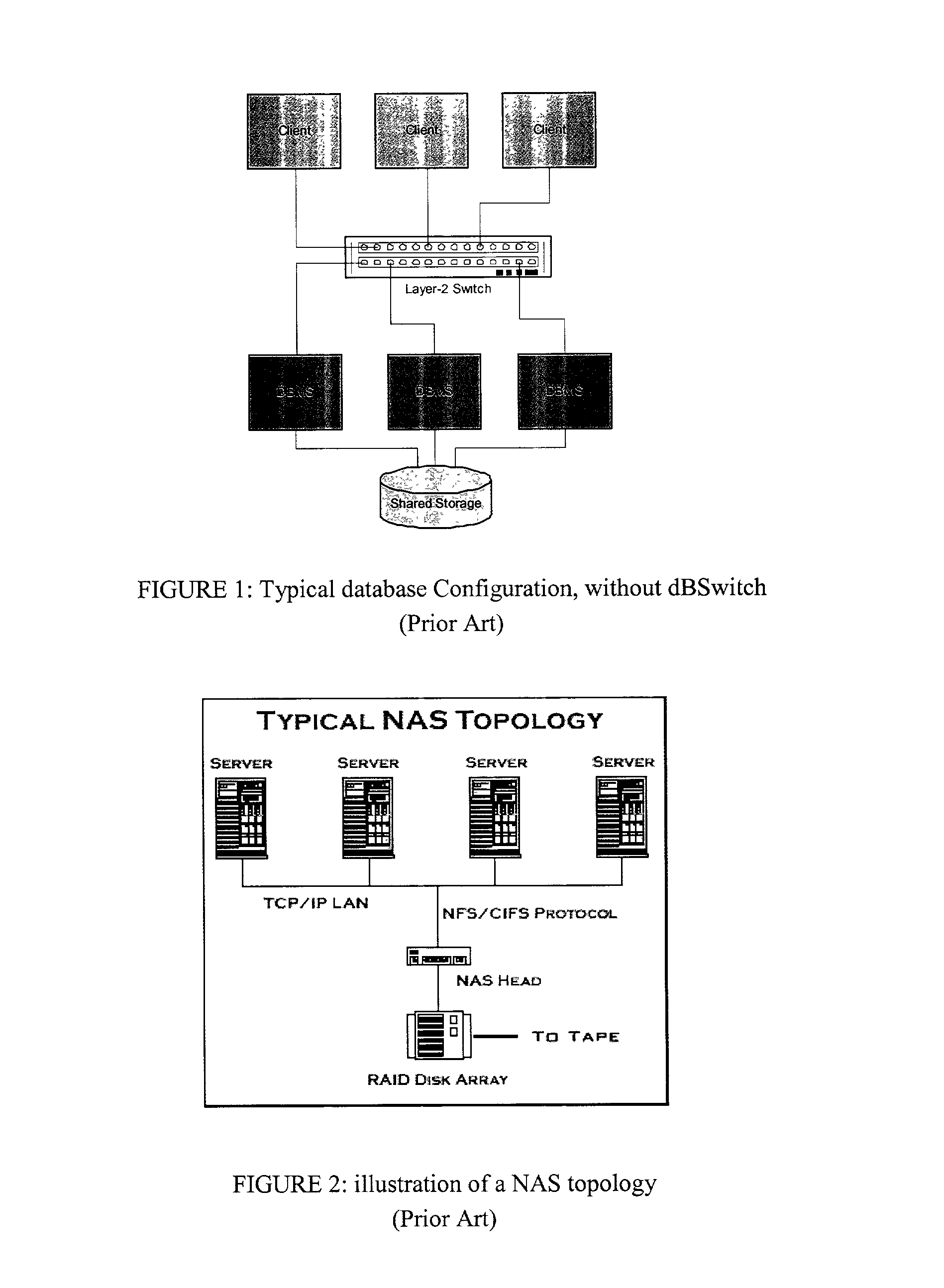
Such dedicated configurations usually result in underutilized resources, limited scalability, high cost, and complex management.
One of the disadvantages of these shared configurations is that they typically compromise performance, quality of service (QoS) and security.
Thus, for example, a database instance serving one application can impede another database instance serving another application that is running on the same database server, either inadvertently or on purpose.
Another disadvantage of these shared configurations is that one database application or a database administrator can access or even modify the contents of another database.
Typically each "primary" database sever is associated with a "backup" server and a replication mechanism is used to keep the backup synchronized with the primary server, though some time lag is unavoidable.
It does not provide for virtualization and sharing of database resources for high utilization as well as high availability.
The '800 patent, however, does not use standard database protocols, and it requires application changes to use the specialized protocol.
If the switcher crashes, clients can no longer communicate with servers.
Changes to the data will necessitate replication and / or repartitioning, which in turn may require switcher reconfiguration, during which its functionality is hampered.
Pre-designation is clearly not an optimal configuration in terms of load balancing or high availability itself (if the backup fails, you're in trouble).

Method used


Image

  • Database Switch enabling a database area network
  • Database Switch enabling a database area network
  • Database Switch enabling a database area network

Examples


example 2

[0100] Example 2 is similar to example 1, but clients, servers and the dBSwitch on the same subnet. In the detailed list below; we also included the virtual addresses as part of the same subnet, demonstrating the indifference of the process to the actual network configuration.

2 Destination Source Direction Type IP Port IP Port Comment 1 Client to Open 172.0.0.105 6000 172.0.0.1 8000 dBSwitch session query 1 dBSwitch Open 172.0.0.105 6000 172.0.0.1 8000 to Server session query 2 Server to Open 172.0.0.1 8000 172.0.0.105 6000 Contains server client session Virtual IP response (172.0.0.105) and port (7300) 3 Client to Data 172.0.0.105 7300 172.0.0.1 8010 dBSwitch 3 dBSwitch Data 172.0.0.105 7300 172.0.0.1 8010 to Server 4 Server to Data 172.0.0.1 8010 172.0.0.105 7300 Client

example 3

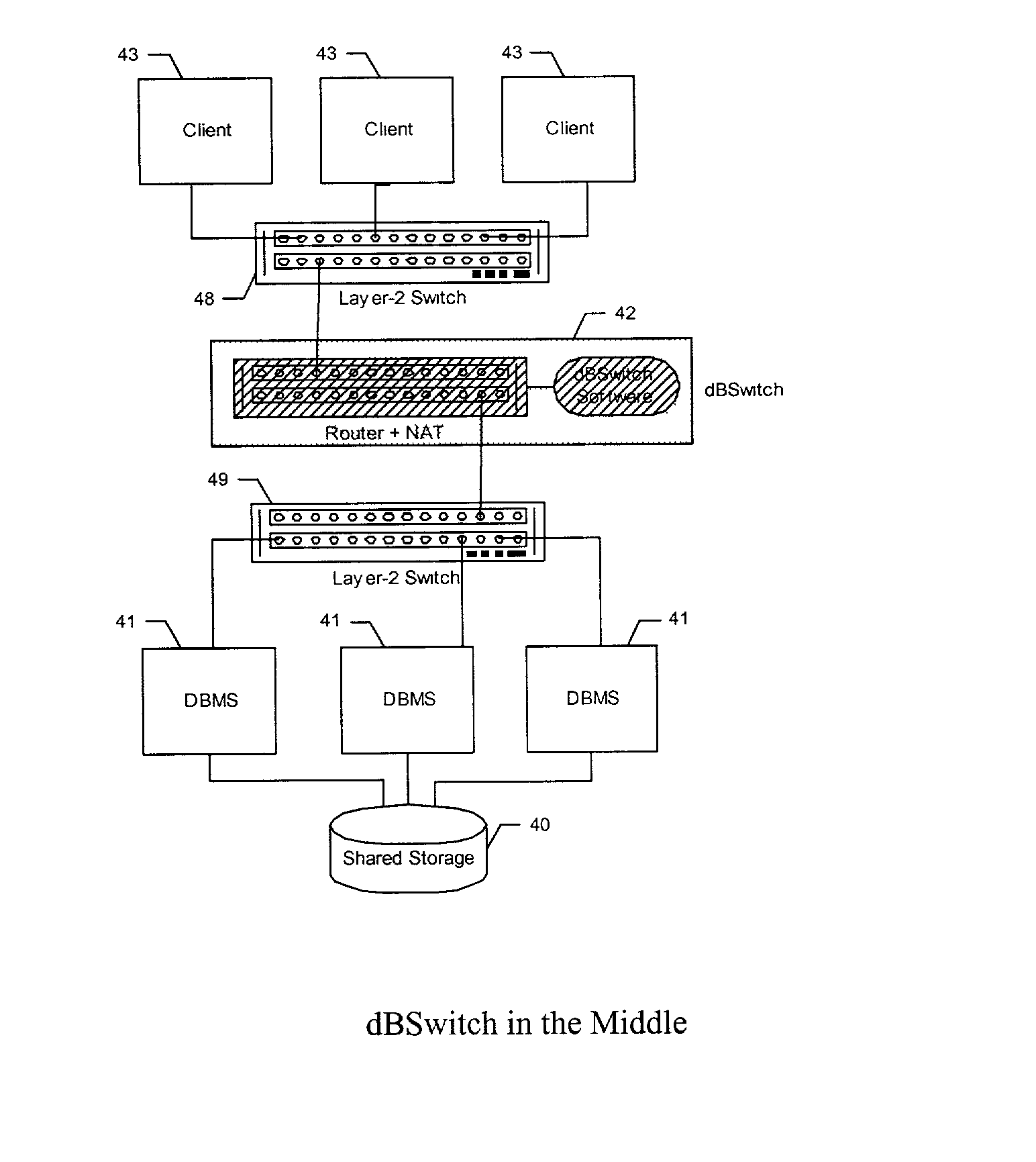
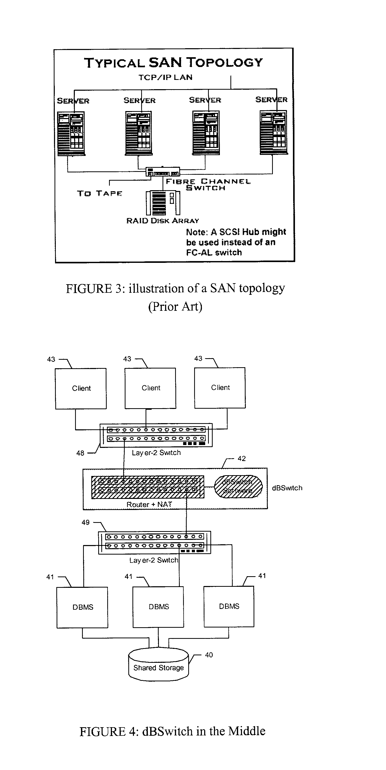
[0101] In example 3 clients specify Virtual Database Service IP addresses but each database server is assigned a single physical IP address. Clients and servers are on separate subnets. The dBSwitch performs routing as well as address translation (NAT), replacing the virtual IP specified in the client request with the physical IP of the database server associated with that service. We are assuming the indirect connection method used with the Oracle DBMS.

[0102] Packet Flow is as Follows:

[0103] 1. Initial Connection--Client to Server

[0104] The initial connection request goes from the client to the dBSwitch. The dBSwitch performs 1-way NAT, changing the destination IP and port to the IP of the database server that provides the requested service and the port number of the Oracle listener for that instance. The dBSwitch then sends the packet to the same IP and port.

[0105] 2. Initial Connection--Server to Client

[0106] The listener sends back to the client a packet containing the IP addres...

example 4

[0113] Example 4 is similar to example 3, but we are assuming a direct connection method, as is the case with the DB2 and SQL Server DBMS (see background). Hence clients always send database packets to the virtual IP address, and the dBSwitch performs NAT on all traffic.

4 Destination Source Direction Type IP Port IP Port Comment 1 Client to Query 172.0.0.10 1430 192.0.0.1 8000 dBSwitch 1 dBSwitch Query 172.0.0.103 4535 192.0.0.1 8000 to Server 2 Server to Response 192.0.0.1 8000 172.0.0.103 4535 dBSwitch 2 dBSwitch Open 192.0.0.1 8000 172.0.0.10 1430 to Client session response

[0114] Non-Database Packet Routing

[0115] Non-database packets can be routed directly from client to database server and back, or using any of the methods described herein for routing database packets though the dBSwitch, for example, direct server return or round trip routing.

[0116] With the Virtual Database Service IP addressing scheme, non-database packets can be directed in two ways, as illustrated in FIG. 7...


PUM


Abstract

A method and system for improving utilization of the typical DBMS client-server configuration is provided. Specifically, the present invention can include a Database Switch (dBSwitch) situated between the applications and database servers in a network, capable of dynamically and transparently connecting applications to databases using standard database servers and standard protocols. The Database Switch appliance performs this database routing in real time, with high bandwidth and negligible latency. The Database Switch enables the formation of a Database Area Network (DAN) architecture, which promotes database virtualization by integrating the database servers, the shared storage, and the interconnecting network, making them appear to be one large, scalable database server. This DAN architecture yields high utilization, high availability, scalability on demand, simplified management and security, in a shared and heterogeneous application environment.

Description

[0001] Not Applicable[0002] Not ApplicableREFERENCE TO MICROFICHE APPENDIX[0003] Not ApplicableFIELD AND BACKGROUND OF THE INVENTION[0004] 1. Field of the Invention[0005] The present invention relates, in general, to database configurations in data networks. More specifically, the present invention relates to the fields of intelligent switching between databases in a computer system and database virtualization.[0006] 2. Description of the Related Art[0007] Databases are generally defined as collections of data arranged for ease and speed of search and retrieval. Databases generally comprise sets of related files that are created and managed by a database management system (DBMS). DBMS can manage any form of data including text, images, sound and video. The data and file structures are typically determined by the DBMS software. Typical database configurations connect applications to dedicated database servers. Such dedicated configurations usually result in underutilized resources, l...

Claims


Application Information

Patent Timeline
Patent Type & Authority Applications(United States)
IPC IPC(8): H04L29/06H04L29/08
CPCH04L67/1036H04L67/1025H04L67/1002H04L67/1006H04L67/1001
Inventor DAR, SHAULGUTHERZ, RONIHECHTRIPIN, BOAZ
Owner DAR SHAUL
Learn More