Small-size engine with forced air cooling system

a technology of forced air cooling and small engine, which is applied in the direction of engine cooling apparatus, machine/engine, fuel air cleaner, etc., can solve the problems of limited space required for engine installation to various work units and irregular engine operation

Inactive Publication Date: 2003-08-21
KAWASAKI HEAVY IND LTD
View PDF8 Cites 30 Cited by
  • Summary
  • Abstract
  • Description
  • Claims
  • Application Information

AI Technical Summary

Benefits of technology

[0008] According to such a structure, since the float chamber of the carburetor is positioned within the fan housing through the cutout defined in the fan housing, the carburetor can be positioned at a location close to the engine body as compared with the design in which the carburetor in its entirety is positioned outside the fan housing and, therefore, an amount of protrusion of the carburetor outwardly of the engine body can be reduced, making it possible to assemble the engine in a compact size. Consequently, limitations on a space available for installing the engine to various work units can be minimized correspondingly. Also, since the float chamber is effectively and sufficiently cooled by the cooling air guided thereto through a cooling air passage defined by the fan housing, it is possible to avoid the irregularity of the engine operation which would result from influences brought about an external heat, for example, heat from the work unit.
[0018] According to the above described construction, the cooling air guided through a cooling air passage formed by the fan housing can cool the float chamber satisfactorily and, therefore, the possibility of the engine operation being irregular under the influence of an external heat can be avoided.

Problems solved by technology

However, it has been found that since in the engine of the structure described above the air cleaner and the carburetor protrude a substantial amount outwardly from the engine body, the space required for an installation of the engine to various work units has been limited.
Also, the engine operation tends to be irregular when the carburetor is strongly affected by an external heat, for example, radiant heat generated from the work unit.

Method used


Image

  • Small-size engine with forced air cooling system
  • Small-size engine with forced air cooling system
  • Small-size engine with forced air cooling system

Examples


Embodiment Construction

[0025] With reference to accompanying drawings, a preferred embodiment of the present invention will now be described.

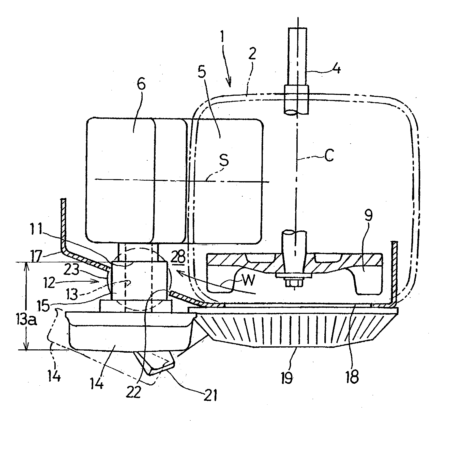
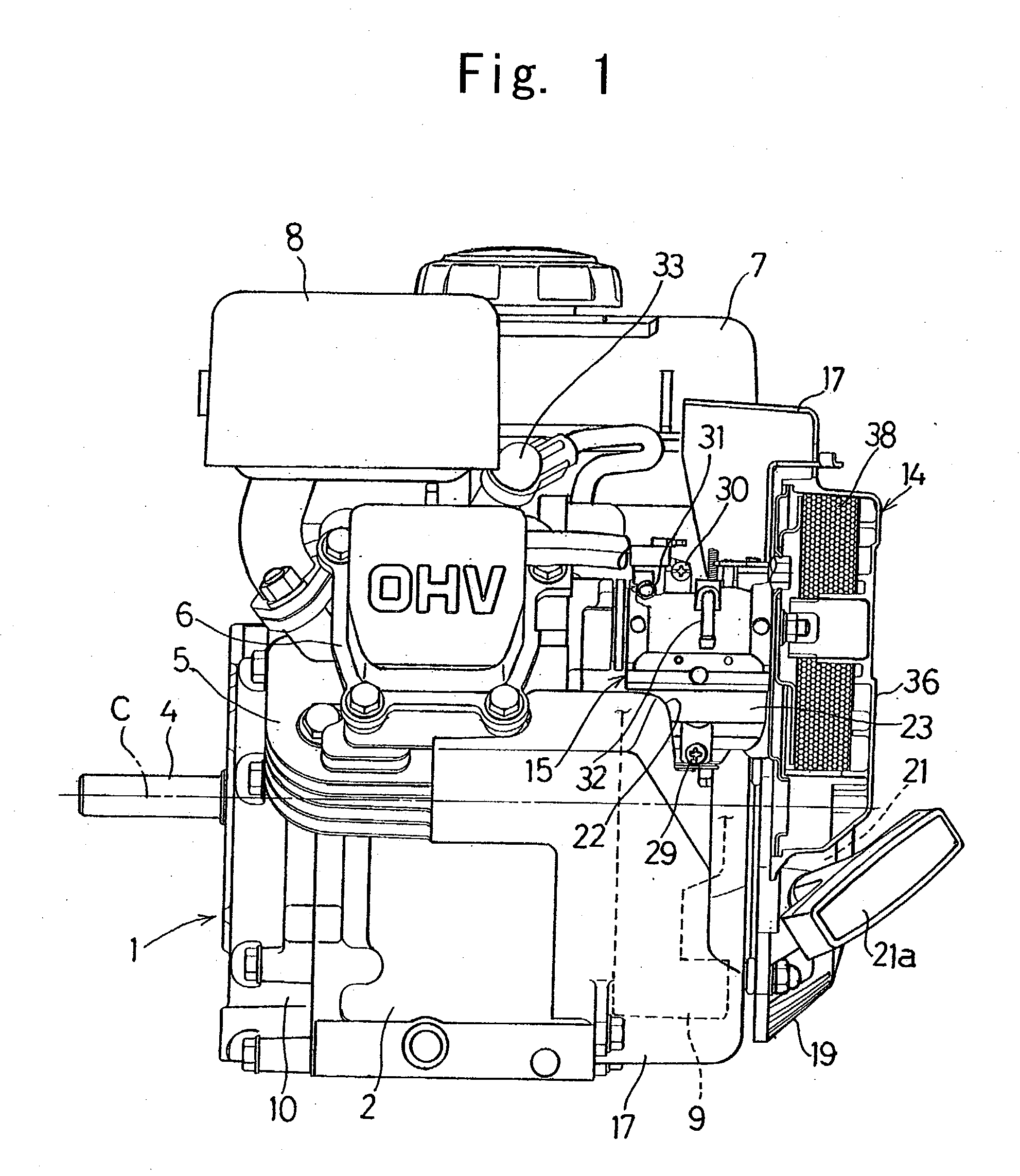
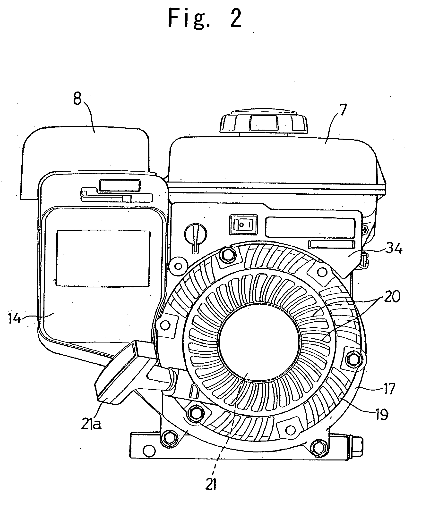
[0026] A small-size engine shown in FIG. 1 is a four cycle, overhead valve engine having a forced air cooling system, that can be utilized as a drive source for various work units such as a compact electric power generator and a water pump. The illustrated engine includes an engine body 1 having a crankcase 2, a cylinder block 5 having a cylinder bore and formed integrally with the crankcase 2, and a cylinder head 6 mounted atop the cylinder block 5. A crankshaft 4 is rotatably supported within and by the crankcase 2. The crankcase 2 has a front opening that is closed by a side cover 10. As best shown in FIG. 3, the cylinder block 5 or the cylinder bore has its longitudinal axis S and is so arranged and so oriented that the longitudinal axis S inclines relative to a horizontal direction and also to a vertical direction and, hence, the cylinder block 5 is diagonally u...


PUM


Abstract

To provide a small-size engine having a forced air cooling system, wherein the amount of protrusion of the air intake system outwardly from the engine body can be minimized and the limitation on the space required for installation of the engine to the various work units can be alleviated, the engine includes a cooling fan (9) mounted on one end of a crankshaft (4) and has a longitudinal axis (S) of a cylinder block (5) inclined relative to a horizontal direction and also to a vertical direction. A fan housing (17) for guiding a cooling air (W) from the cooling fan (9) towards a cylinder block (5) and a cylinder head (6) is formed with a cutout (22) through which a float chamber (23) of a carburetor (15) is positioned inside the fan housing (17).

Description

[0001] 1. Field of the Invention[0002] The present invention relates to a small-size engine having a forced air cooling system for cooling a cylinder block and a cylinder head with a cooling air induced by a cooling fan.[0003] 2. Description of the Prior Art[0004] A small-size engine having a forced air cooling system is known in which a cylinder block of an engine body has a longitudinal axis inclined relative to a horizontal direction and also to a vertical direction, and in which a fan housing is provided on one side of the engine body to cover a cooling fan mounted on one end of a crankshaft so that a cooling air induced by the cooling fan can be guided through the fan housing towards the cylinder block and a cylinder head of the engine body. In such arrangement, an air cleaner and a carburetor defining an air intake passage of the engine are mounted so as to protrude outwardly of the fan housing to secure a cooling air passage within the fan housing. See, for example, the Japan...

Claims


Application Information

Patent Timeline
Patent Type & Authority Applications(United States)
IPC IPC(8): F02B67/00F01P1/02F01P5/06F02B63/02F02B75/02F02B75/16F02M35/04
CPCF01P1/02F01P5/06F02B2275/22F02B75/16F02B2075/027F02B63/02
Inventor NAKAMIZO, KEIICHITAKAHASHI, KOJIMIKI, YUKIO
Owner KAWASAKI HEAVY IND LTD
Why Eureka
Try Eureka