Wiper blade to clean windshields, in particular of automobiles

a technology for windshields and blades, which is applied in the field of windshield cleaning, can solve the problems of increased friction between the support element and the wind deflection strip, unfavorable squeaking noise,

Active Publication Date: 2003-08-28
ROBERT BOSCH CORP
View PDF5 Cites 119 Cited by
  • Summary
  • Abstract
  • Description
  • Claims
  • Application Information

AI Technical Summary

Problems solved by technology

These tensions can negatively impact the wipe results and moreover can result in undesirable squeaking noises during wiper operation due to the generation of a braking effect at the flexible rails that disrupts this relative motion, caused by the friction of the material needed to make up the wind deflection strip, which

Method used


Image

  • Wiper blade to clean windshields, in particular of automobiles
  • Wiper blade to clean windshields, in particular of automobiles
  • Wiper blade to clean windshields, in particular of automobiles

Examples


Embodiment Construction

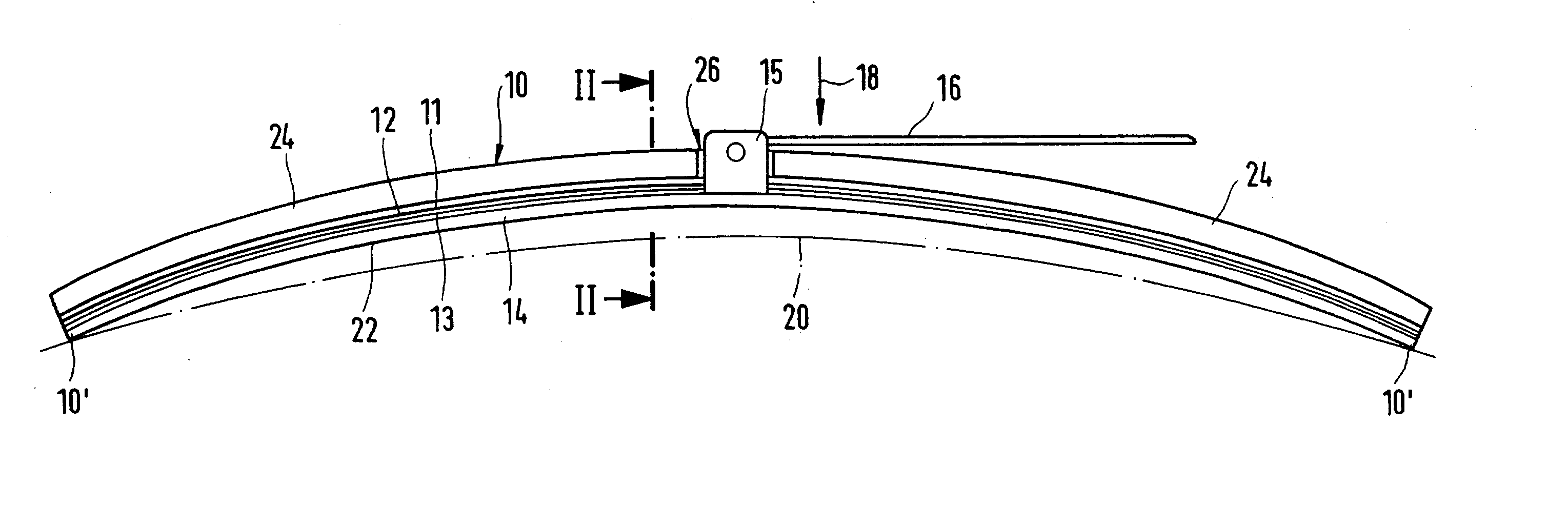
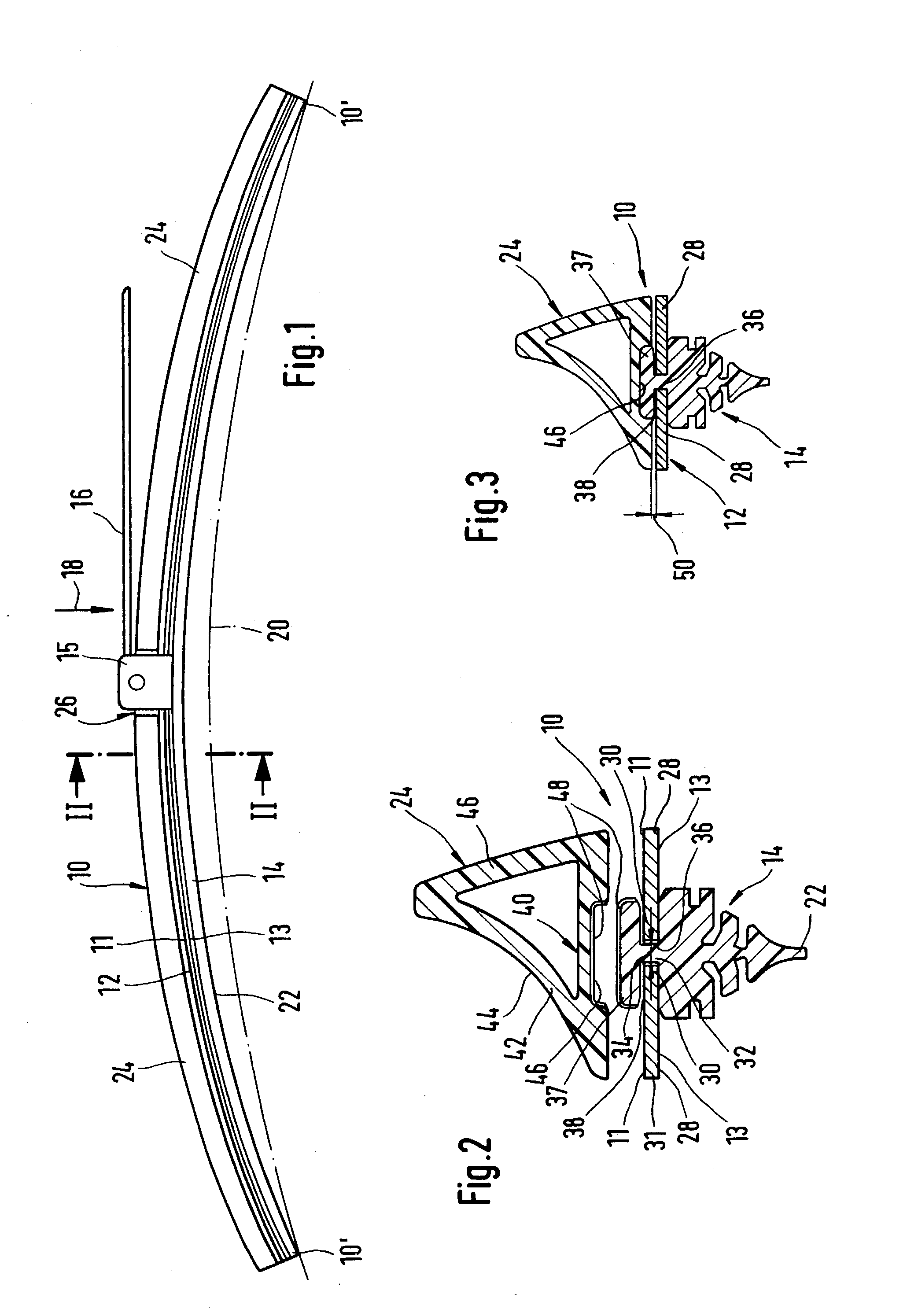
[0038] A wiper blade 10 shown in FIG. 1 has an elongated belt-shaped, flexible spring support element 12 with an elongated, elastic rubber wiper strip 14 attached parallel to the longitudinal axis to its bottom belt side or surface 13 facing the windshield. At the upper belt side or surface 11 of the support element 12, which in this exemplary embodiment consists of two flexible rails, said surface facing away from the windshield, is a section 15 of a wiper blade connector that is located in the center section of the support element and connected to it. With the help of this connector, the wiper blade 10 can be removably connected in a hinged fashion to a driven wiper arm 16 that is shown partially in FIG. 1. The wiper arm 16, which moves perpendicular to its longitudinal direction in a pendulum fashion, is loaded in the direction of an arrow 18 toward the windshield to be wiped--for example toward the windshield of an automobile--the surface of which is indicated by a dot-dashed li...


PUM


Abstract

A wiper blade is proposed with which to clean windshields, in particular of automobiles. The wiper blade (10) has an elongated belt-shaped, flexible spring support element (12), with a separate first component designed as an elastic rubber wiper strip (14) that can be pressed against the windshield (20) located at the bottom belt surface (13) of the support element and with a separate second component located at the other upper belt surface (11) of the support element (12) that is designed as a wind deflection strip (24) that extends at least along a longitudinal section of the wiper blade (10). A particularly low-disruption wiper blade results if the two components (14, 24) are connected together at their sides facing one another.

Description

PRIOR ART[0001] In wiper blades that are, instead of the so-called stirrup system (DE-OS 15 05257), provided with an elongated belt-shaped, flexible spring support element for the purposes of distributing a force originating from the wiper arm so as to properly press the wiper strip against the windshield to be wiped, the unloaded support element must exhibit a specific natural curvature that is greater than the largest curvature in the wipe field of the windshield to be wiped. When the wiper blade is pressed against the windshield, it first touches the vehicle windshield (20) at the two ends 10' of its wiper strip only (FIG. 1). Under the effect of a force originating from the wiper arm, the entire length of the wiper strip is then pressed against the windshield, wherein the support element is placed under tension. This tension must exist along the entire wipe field passed over by the wiper blade --within certain limits--, even if the radii of curvature of spherically curved vehicl...

Claims


Application Information

Patent Timeline
IPC IPC(8): B60S1/38
CPCB60S1/381B60S2001/3817B60S1/3879B60S1/3848
Inventor WEILER, MICHAELZIMMER, JOACHIMDIETRICH, JAN
Owner ROBERT BOSCH CORP
Why Eureka
Try Eureka