Mounting method and device

a mounting method and a technology of a mounting device, applied in the direction of non-electric welding apparatus, manufacturing tools, solventing apparatus, etc., can solve the problems of ineffective primary oxidation prevention methods, inability to obtain the desired bonding state between the bump and the substrate, and secondarily oxidizing the bump by heating under oxidation

Inactive Publication Date: 2003-09-04
TORAY ENG CO LTD +1
View PDF6 Cites 29 Cited by
  • Summary
  • Abstract
  • Description
  • Claims
  • Application Information

AI Technical Summary

Problems solved by technology

In such a flip-chip process using a solder bump, there is a fear that the solder bump is primarily oxidized before bonding step by being touched with an atmosphere, etc., and further, there is a fear that the bump is secondarily oxidized by heating under an oxidization gas atmosphere at the time of heat bonding or a time immediately before the heat bonding.
If such a primary or secondary oxidation occurs, namely, if there exists an oxide on the surface of the bump, there is a fear that a desired bonding state cannot be obtained between the bump and the pad of the substrate.
However, because this conventional method basically aims to prevent secondary oxidation, the method is substantially not effective for preventing primary oxidation such as one described above.
Therefore, it seems to be difficult to apply this method to the bonding of a chip having a solder bump which basically is thermally bonded and a substrate having a pad which is formed from a material different from that of the solder bump.

Method used


Image

  • Mounting method and device
  • Mounting method and device
  • Mounting method and device

Examples


Embodiment Construction

[0023] Hereinafter, desirable embodiments of the present invention will be explained referring to figures.

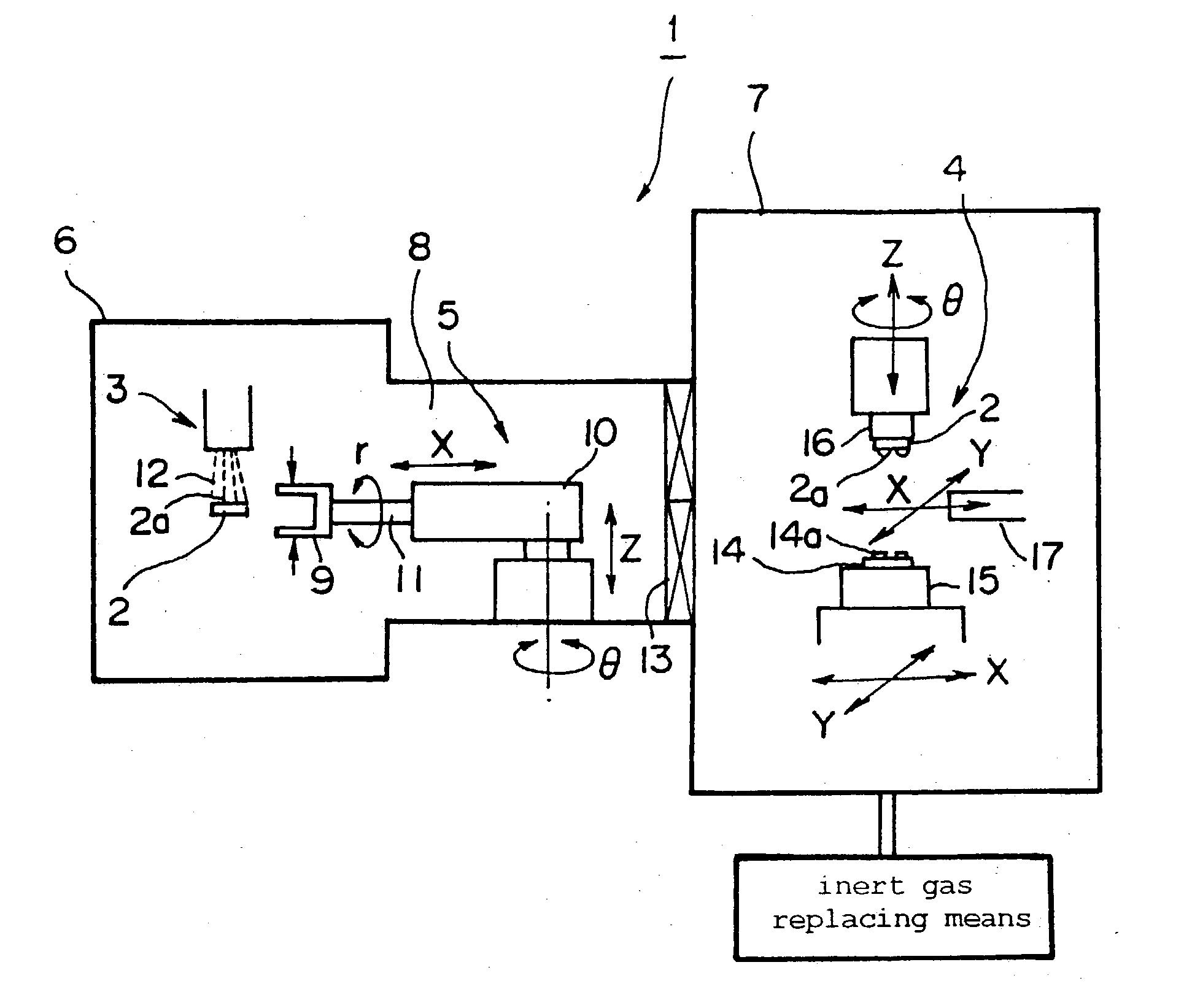
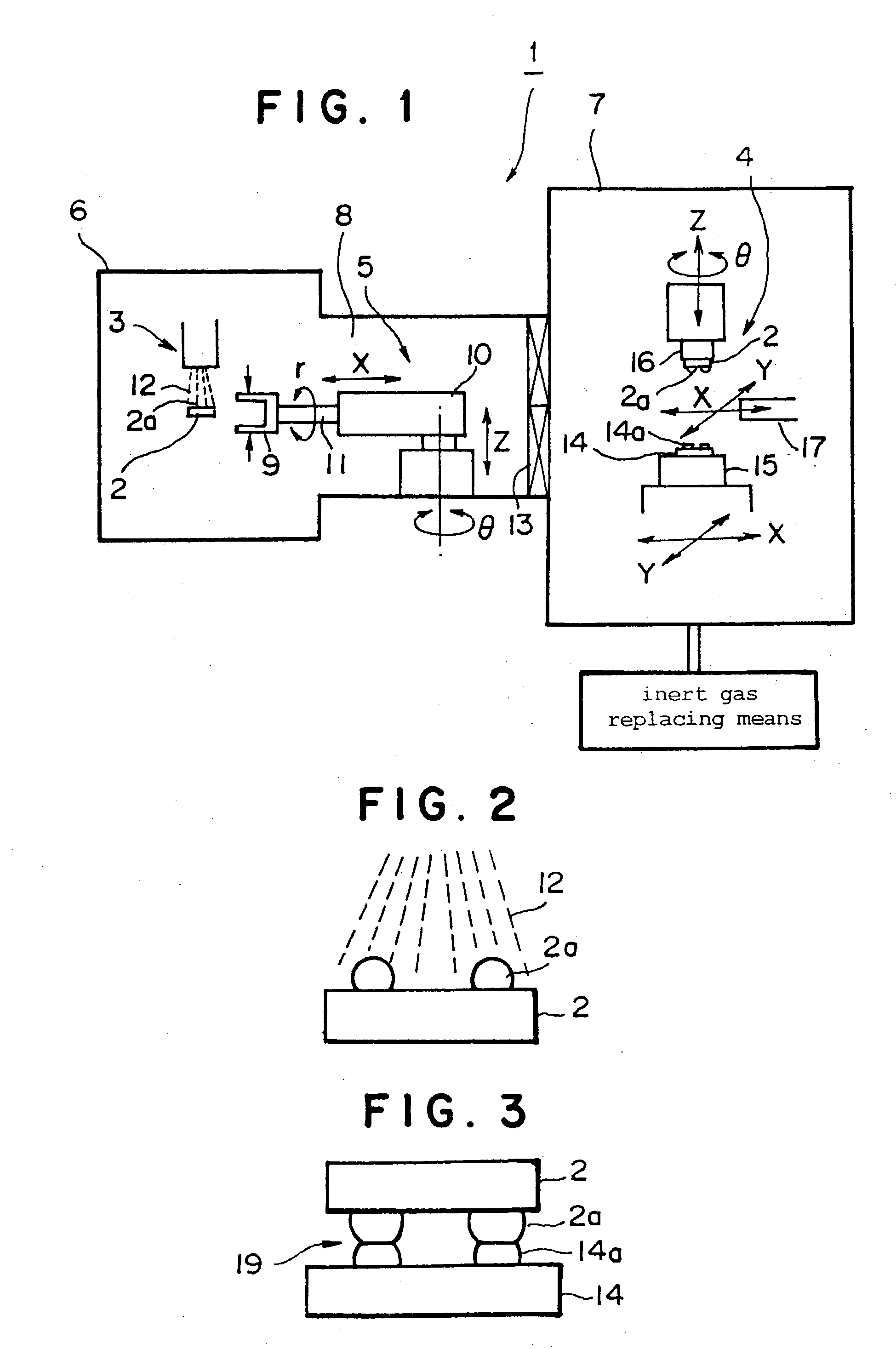
[0024] FIGS. 1 to 3 show a mounting device according to an embodiment of the present invention. In FIG. 1, numeral 1 indicates the whole of a mounting device, and the mounting device 1 comprises a cleaning means 3 for cleaning at least solder bumps 2a provided as metal joint parts on a first object 2 (for example, an IC chip), a bonding means 4 for bonding the solder bumps 2a of the first object 2 cleaned by the cleaning means 3 to pads 14a provided on a second object 14 (for example, a substrate), and a conveying robot 5 provided as a conveying means for being disposed between the cleaning means 3 and the bonding means 4 and for conveying at least the first object 2 cleaned by the cleaning means 3 to the bonding means 4.

[0025] In this embodiment, cleaning means 3 is installed in a cleaning chamber 6, and bonding means 4 is installed in a bonding chamber 7. Cleaning chamber 6 an...


PUM

PropertyMeasurementUnit
atmospheric pressureaaaaaaaaaa
concentrationaaaaaaaaaa
temperatureaaaaaaaaaa

Abstract

A mounting method for bonding a first object having a metal joint part to a second object, comprising the steps of cleaning at least the surface of the metal joint part of the first object by irradiating an energy wave or energy particle beam, and thermally bonding the cleaned metal joint part of the first object to a portion to be bonded of the second object by heating in a special gas atmosphere, and a device thereof. In the mounting, the primary and secondary oxidations of the metal joint part can be efficiently prevented, and thereby highly reliable bonding can be carried out.

Description

[0001] The present invention relates to mounting method and device for bonding an object such as a chip having a metal joint part such as a solder bump to another object such as a substrate, and specifically to mounting method and device in which the oxidation of the metal joint part can be efficiently prevented.BACKGROUND ART OF THE INVENTION[0002] A mounting method for bonding an object with a metal joint part such as a solder joint part to another object, for example, a chip mounting method for forming a solder bump on a chip, approaching the chip to a substrate at a face-down condition, bringing the solder bump into contact with a pad of the substrate, and thereafter heating and melting the bump of the chip to bond it to the pad of the substrate, is well known. In such a flip-chip process using a solder bump, there is a fear that the solder bump is primarily oxidized before bonding step by being touched with an atmosphere, etc., and further, there is a fear that the bump is seco...

Claims


Application Information

Patent Timeline
Patent Type & Authority Applications(United States)
IPC IPC(8): B23K1/20H05K3/34H01L21/00H01L21/60
CPCB23K1/206H01L2924/014H01L21/67109H01L24/75H01L24/81H01L2224/13111H01L2224/75H01L2224/75252H01L2224/75743H01L2224/81054H01L2224/81121H01L2224/81801H01L2924/01004H01L2924/01047H01L2924/01079H01L2924/01082H01L2924/14H05K3/3426H01L2924/01006H01L2924/01033H01L2924/0105H01L21/67028H01L2924/12042H01L2224/81075H01L2224/81093H01L2224/81H01L2924/00H01L21/60
Inventor SUGA, TADATOMOYAMAUCHI, AKIRA
Owner TORAY ENG CO LTD
Why Eureka
Try Eureka