Reaction frame for a wafer scanning stage with electromagnetic connections to ground

a scanning stage and reaction frame technology, applied in the field of scanning stage apparatus, can solve the problems of vibration in the base structure, the performance of a precision instrument, and the inability to properly form products formed using the precision instrumen

Inactive Publication Date: 2003-09-11
NIKON CORP
View PDF0 Cites 18 Cited by
  • Summary
  • Abstract
  • Description
  • Claims
  • Application Information

AI Technical Summary

Problems solved by technology

When the performance of a precision instrument is adversely affected, as for example by reaction forces or by vibrations, products formed using the precision instrument may be improperly formed and, hence, defective.
For instance, a photolithography machine which is subjected to vibratory motion may cause an image projected by the photolithography machine to move, and, as a result, be aligned incorrectly on a projection surface such as a semiconductor wafer surface.
Such reaction forces may cause the base structure to move, and may also cause vibrations to be induced in the base structure.
Movement of the base structure renders it more difficult to position the stage, as motion of the base structure causes the stage to move.
As will be appreciated by those skilled in the art, forces or vibrations generated within a photolithography apparatus or exposure apparatus may cause issues relating to photolithography and exposure operations.
The accuracy associated with such operations may be compromised when forces and vibrations affect the positioning of wafers or reticles, for example.
However, reaction forces transmitted through a reaction frame may result in vibrations being induced within the reaction frame which, in turn, may adversely affect the performance of the photolithography apparatus or exposure apparatus.
Additionally, ground vibrations which may be transmitted from the ground to the reaction frame may affect the stage.
The transmission of high frequency reaction forces is often considered to be undesirable, due to vibrations which may be induced in connection to ground 122 and subsequently transferred to other structures on the ground.

Method used


Image

  • Reaction frame for a wafer scanning stage with electromagnetic connections to ground
  • Reaction frame for a wafer scanning stage with electromagnetic connections to ground
  • Reaction frame for a wafer scanning stage with electromagnetic connections to ground

Examples


Embodiment Construction

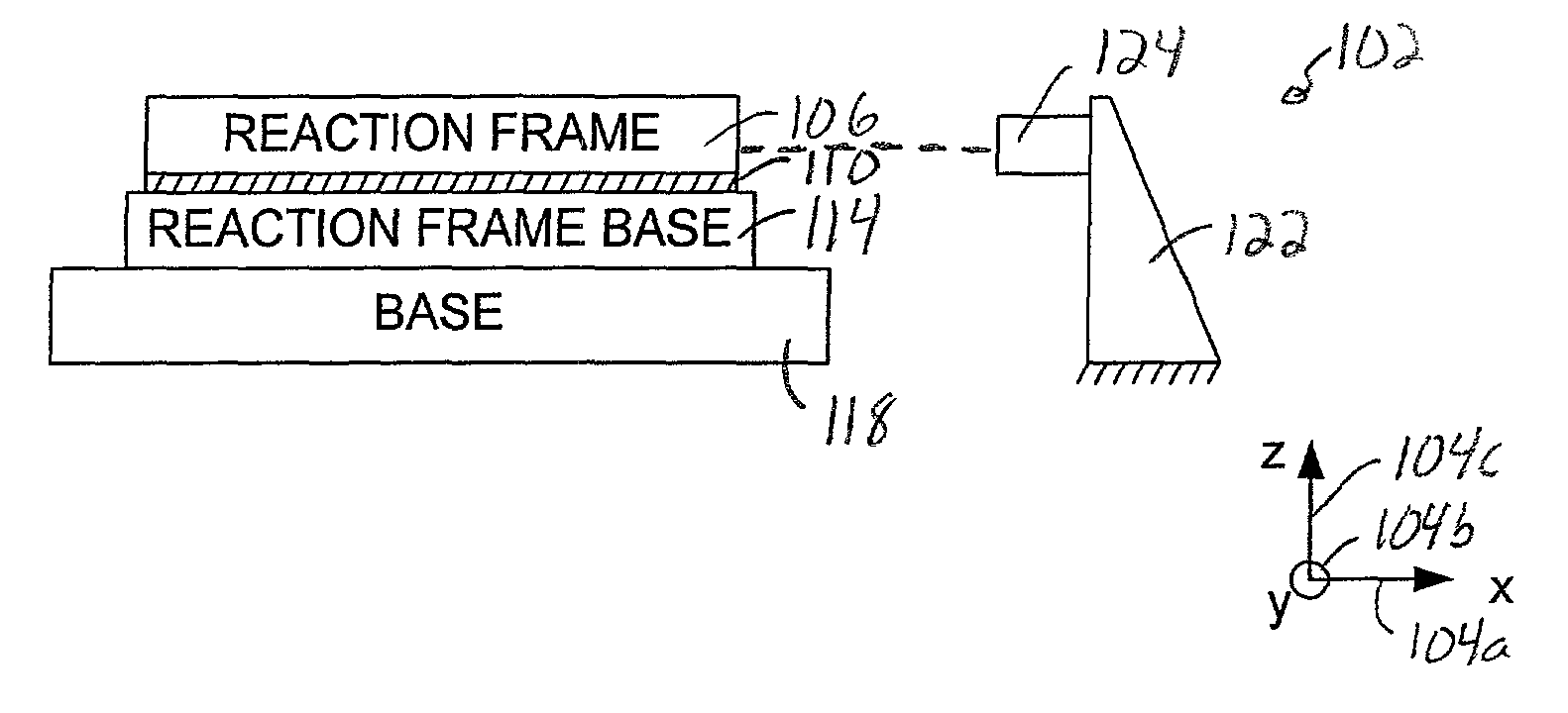
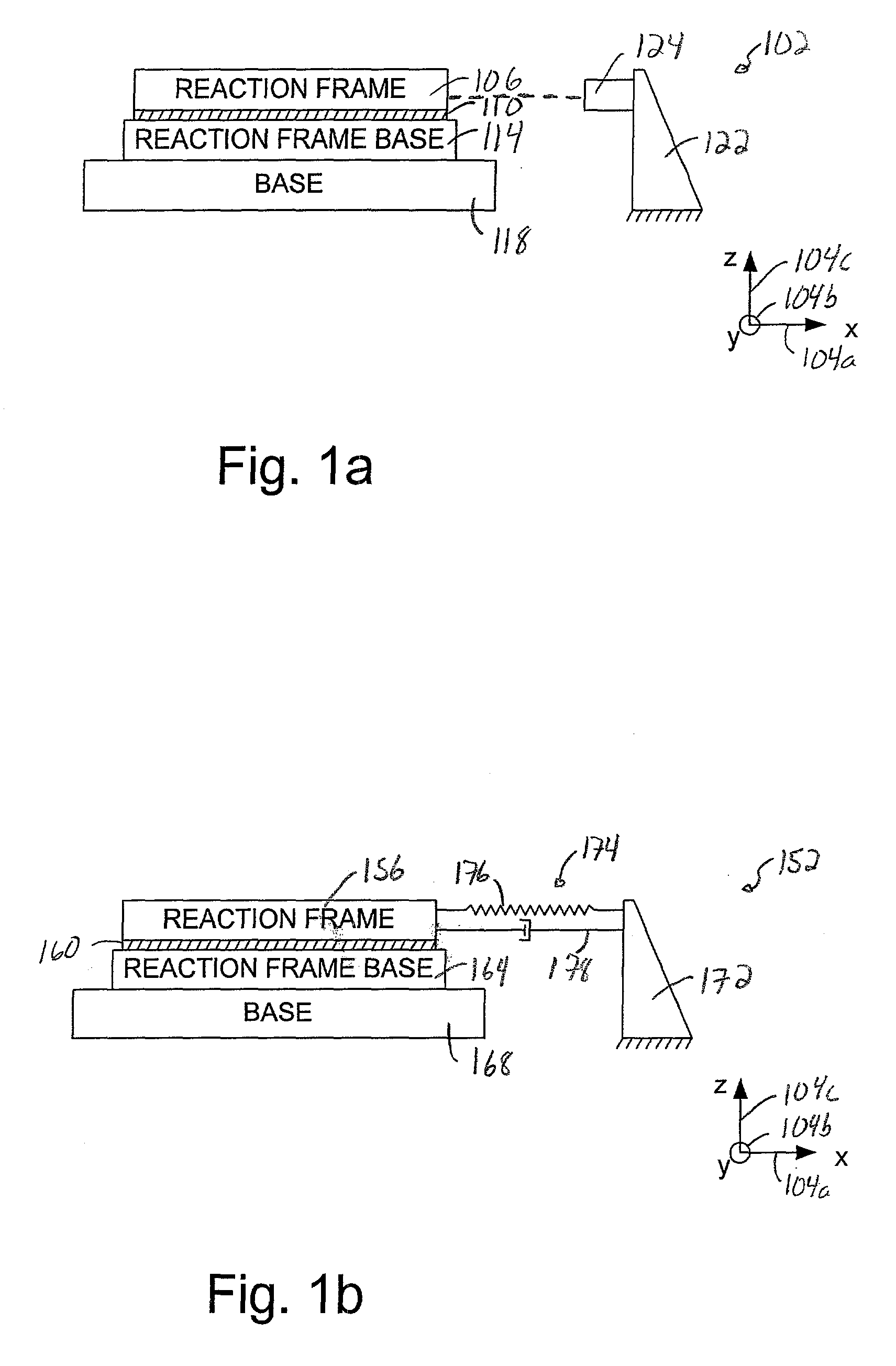
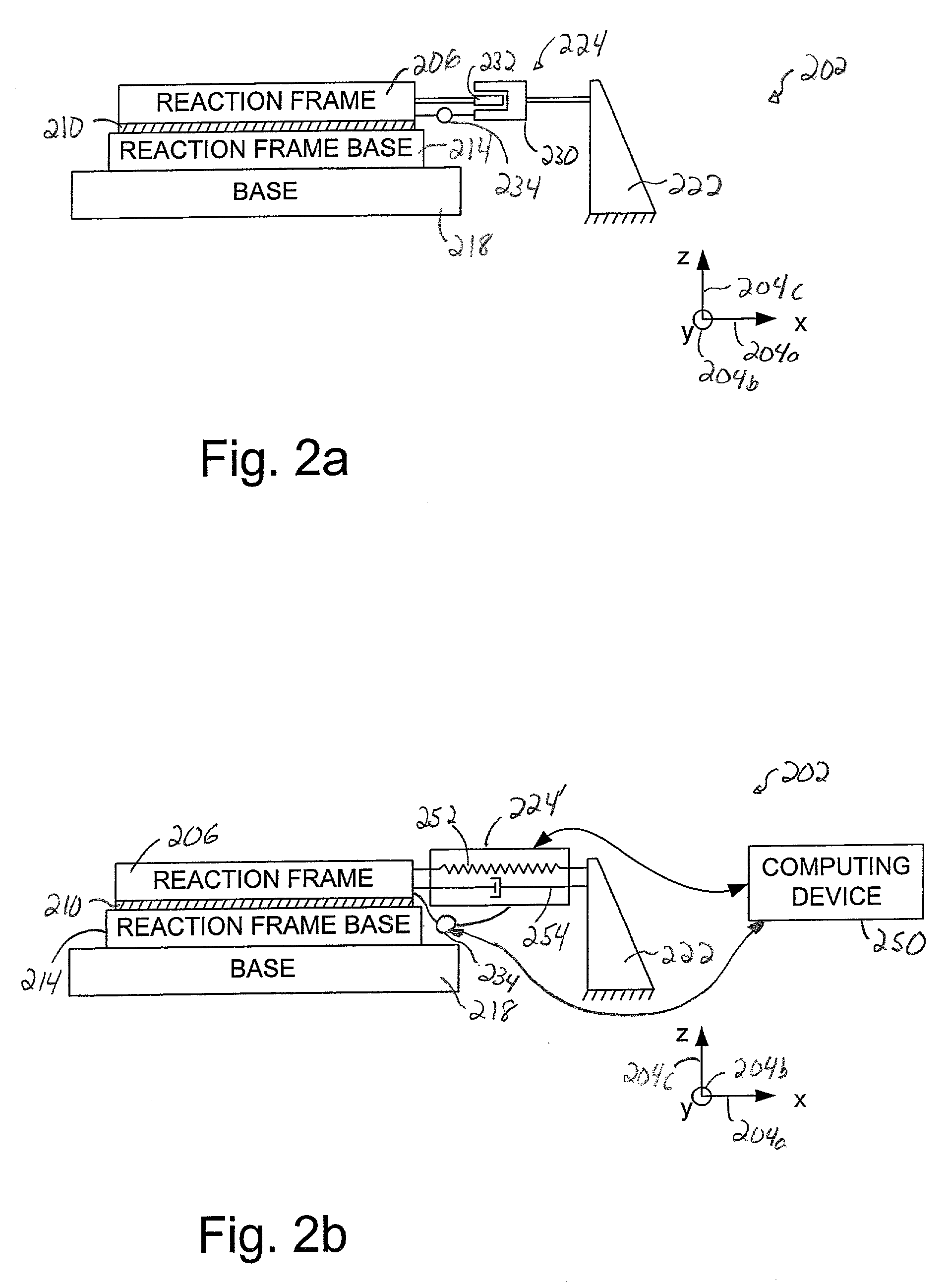
[0034] Reducing reaction forces and vibrations within an apparatus such as a photolithography apparatus or an exposure apparatus is important to ensure that semiconductor fabrication processes may be implemented efficiently and accurately. To reduce reaction forces, reaction frames are often used to isolate reaction forces of motors used to move stages by transmitting at least some of the forces associated with moving the stages to ground. However, ground vibrations and vibrations induced by the reaction forces may be transmitted through the reaction frame into the overall apparatus, thereby compromising the performance of the overall apparatus, e.g., by affecting the accuracy with which stages may move.

[0035] By adding stiffness and damping to a connection between a reaction frame and ground, the amount of vibrations induced in the reaction frame by reaction forces may be substantially minimized. In addition, the coupling between ground vibrations and the reaction frame may also be...


PUM

PropertyMeasurementUnit
frequencyaaaaaaaaaa
frequencyaaaaaaaaaa
wavelengthaaaaaaaaaa

Abstract

Methods and apparatus for isolating vibrations associated induced by reaction forces and ground vibration are disclosed. According to one aspect of the present invention, a scanning stage apparatus includes a stage base, a stage, a driver, and a reaction frame. The stage moves over the stage base in a first translational direction, a second translational direction, and a first rotational direction. The driver causes the stage to move, and also causes at least one reaction force to be created when the stage moves. The reaction frame at least partially supports the driver, and along with the driver, is substantially decoupled from the stage base. The reaction force is arranged to be transmitted to the reaction frame. The electromagnetic coupling electromagnetically couples the reaction frame to a ground, and provides a stiffness and a damping between the reaction frame and the ground.

Description

[0001] The present application is related to U.S. patent application Ser. No. 09 / 932,410, entitled "Reaction Force Isolation Frame," filed Aug. 17, 2001, which is incorporated herein by reference in its entirety.[0002] 1. Field of Invention[0003] The present invention relates generally to semiconductor processing equipment. More particularly, the present invention relates to a scanning stage apparatus which includes electromagnetic connections to a grounding surface which are effective to isolate vibrations induced by reaction forces created by movement of a stage within the scanning stage apparatus, and vibrations associated with the grounding surface.[0004] 2. Description of the Related Art[0005] For precision instruments such as photolithography machines which are used in semiconductor processing, factors which affect the performance, e.g., accuracy, of the precisions instruments generally must be dealt with and, insofar as possible, eliminated. When the performance of a precisio...

Claims


Application Information

Patent Timeline
Patent Type & Authority Applications(United States)
IPC IPC(8): G03F7/20
CPCG03F7/70833G03F7/70766
Inventor HAZELTON, ANDREW J.
Owner NIKON CORP
Why Eureka
Try Eureka