Cutting insert for grooving and profiling

a cutting insert and profiling technology, applied in the direction of cutting inserts, shaping cutters, manufacturing tools, etc., can solve the problems of scrapping components, operation shutdowns, and the ability of said cutting inserts to give good chip control

Inactive Publication Date: 2003-09-11
SANDVIK INTELLECTUAL PROPERTY AB
View PDF3 Cites 19 Cited by
  • Summary
  • Abstract
  • Description
  • Claims
  • Application Information

AI Technical Summary

Problems solved by technology

Long, uncontrollable chips may easily cause operational shutdowns and make it necessary to scrap components.
In practice, it has turned out that the ability of said cutting insert to give good chip control in a large a number of turning operations irrespective of feeding direction and over a larg

Method used


Image

  • Cutting insert for grooving and profiling
  • Cutting insert for grooving and profiling
  • Cutting insert for grooving and profiling

Examples


Embodiment Construction

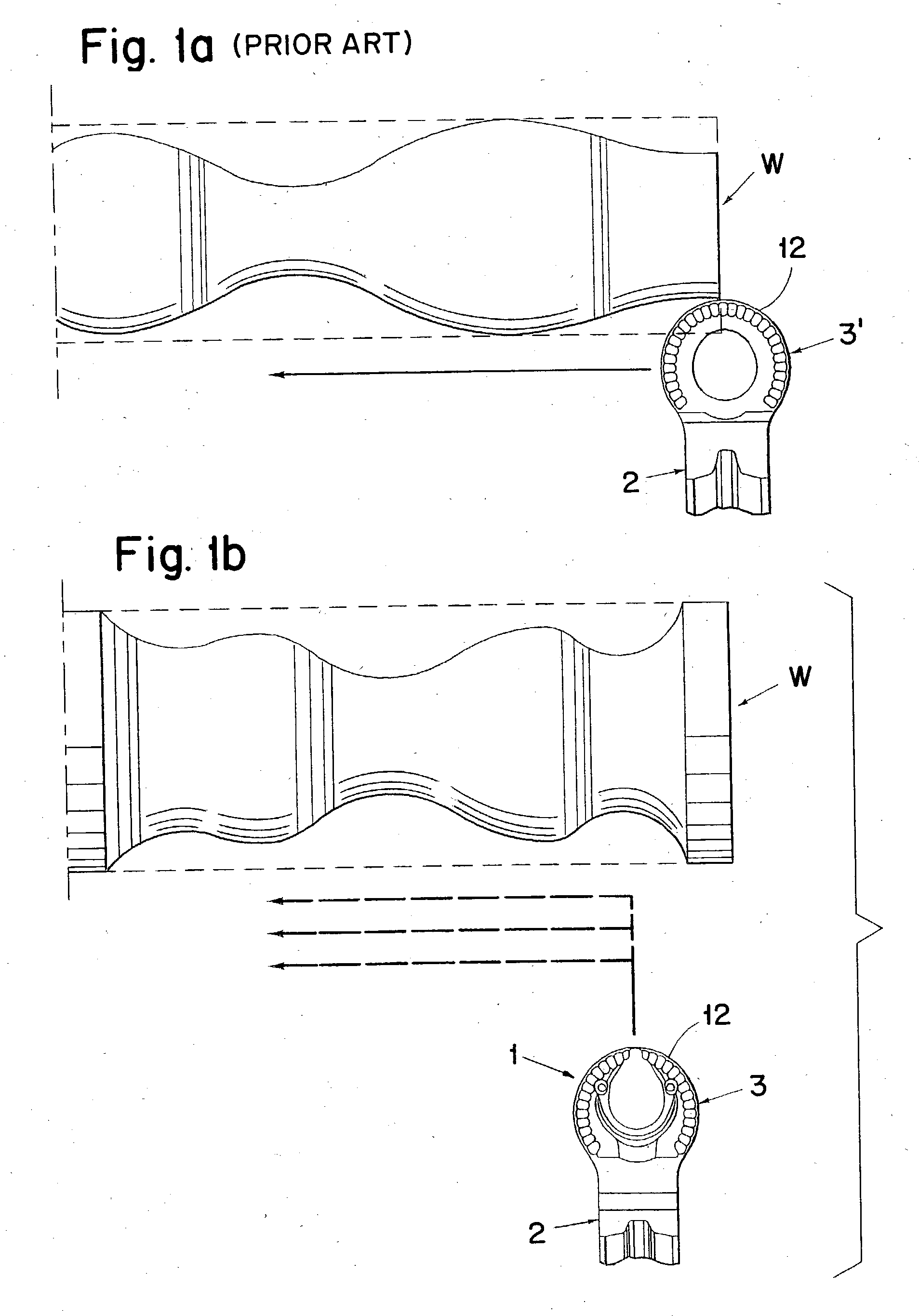
[0030] FIG. 1a shows a workpiece (W) and a cutting insert (2, 3') according to prior art. The cutting insert is most suited for profiling operations wherein the cutting insert moves essentially parallel to the center line of the workpiece. This cutting insert is most suited to commence at the outer end of the workpiece and for machining with low cutting data.

[0031] FIG. 1b shows a work-piece (W) and a cutting insert (2, 3) according to the invention. The cutting insert is suited for all profiling and longitudinal turning operations, and also those that involve a heavy plunging operation.

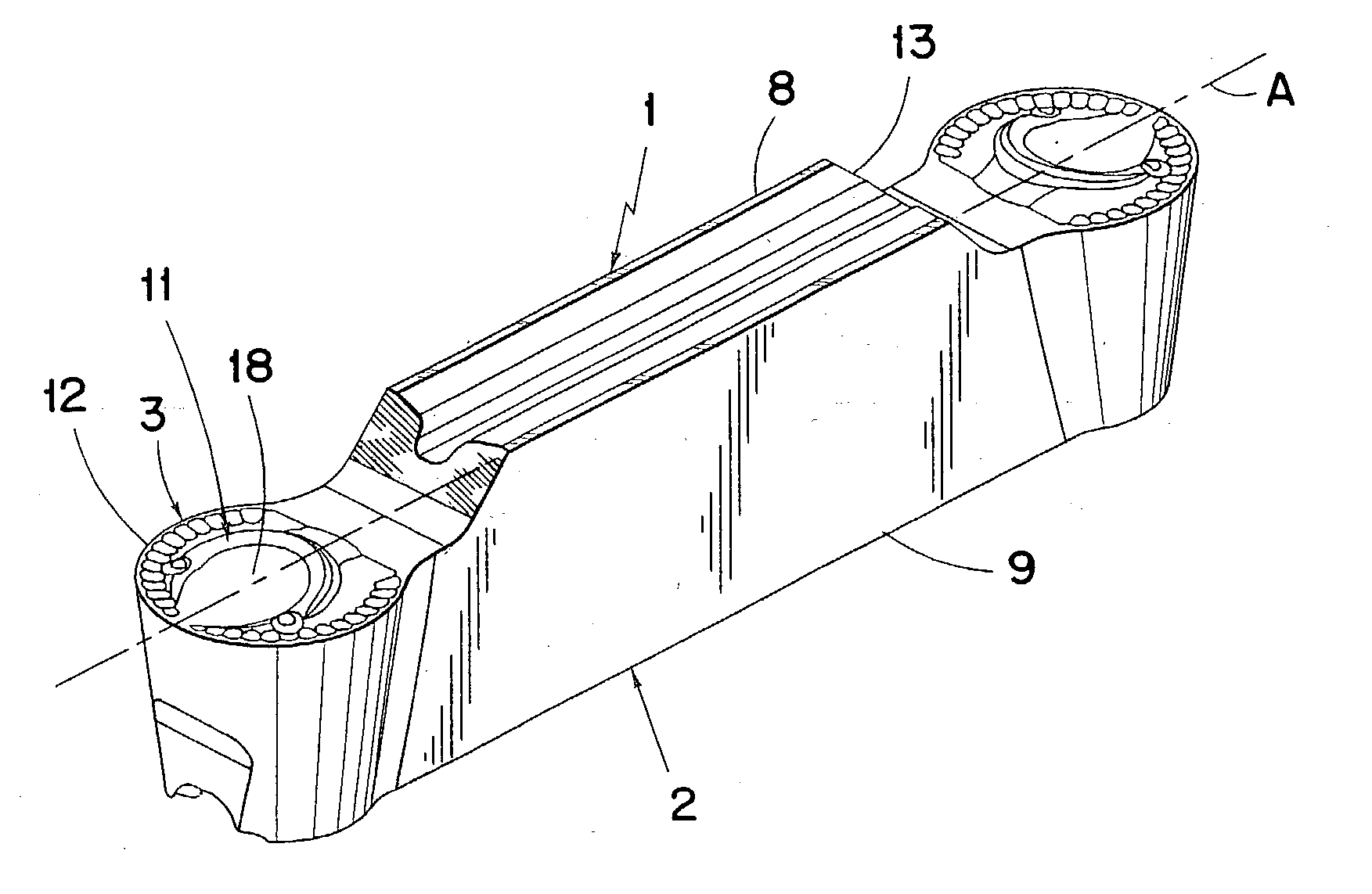
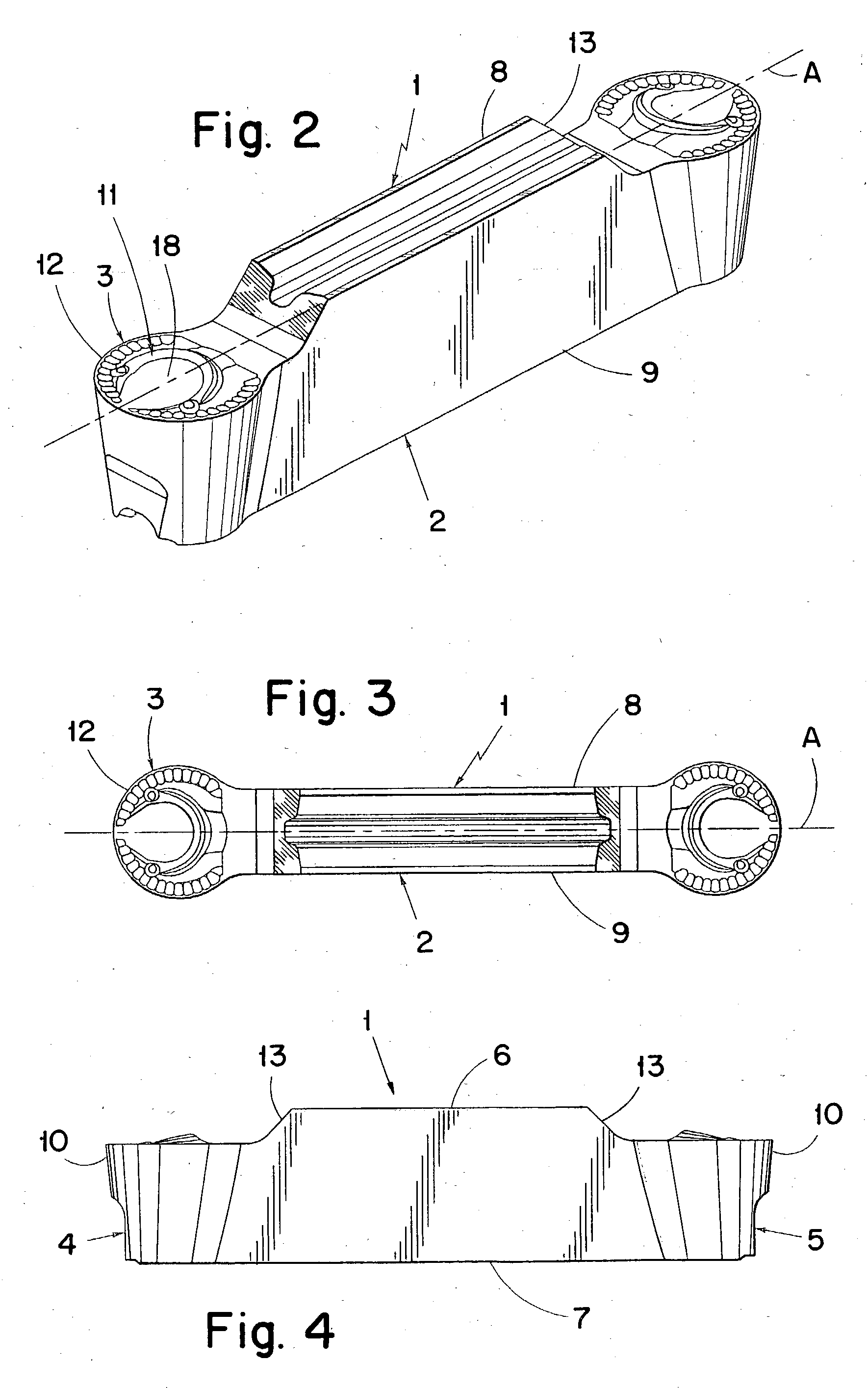
[0032] FIGS. 2-5 show a cutting insert (1) for grooving and profiling operations according to the invention comprising a body having a shaft part (2) for clamping in a suitable tool holder. The cutting insert is produced of a suitable hard material, such as cemented carbide, ceramics or the like which furthermore may be coated. The body comprises two cutting heads (3), two end surfaces (4, 5), two si...


PUM

PropertyMeasurementUnit
Angleaaaaaaaaaa
Angleaaaaaaaaaa
Angleaaaaaaaaaa

Abstract

A cutting insert for grooving and parting as well as profiling and longitudinal turning of metallic work-pieces, includes a shaft part and at least one cutting head. There is a front end surface at the front end of the cutting insert, and a rear end surface at the rear end of the cutting insert. The shaft part includes a top side, a bottom side and side surfaces extending between the tope and bottom two sides. The cutting head carries a cutting edge defined by the intersection between a chip surface and a clearance surface. The cutting edge has a circular shape and has mainly a constant curvature between the ends thereof. The chip side of the cutting head is provided with a first chip-forming device placed immediately inside the cutting edge.

Description

[0001] This application claims priority under 35 U.S.C. .sctn.119 to Patent Application Serial No. 0200310-1 filed in Sweden on Jan. 31, 2002, the entire content of which is hereby incorporated by reference.[0002] The present invention relates to a cutting insert for grooving and parting work-pieces. The insert is of the type comprising a shaft part having at least one cutting head thereon. An end surface is disposed at the front end of the cutting insert, and a rear end surface is disposed at the rear end of the cutting insert. The shaft part comprises a top side, a bottom side as well as two sides side surfaces extending between the same. The cutting head carries a cutting edge which is defined by the intersection between a chip side and a clearance side. The cutting edge has a circular shape and has mainly the same (constant) curvature up to the ends thereof, the chip side of the cutting head is provided with a first chip-forming device placed immediately inwards from the cutting...

Claims


Application Information

Patent Timeline
IPC IPC(8): B23B27/00B23B27/14B23B27/04
CPCB23B27/045B23B2200/321B23B2200/323Y10T407/235Y10T407/245Y10T407/24B23B2265/34B23B27/06
Inventor ANDERSSON, CLAESFRANSSON, HAKAN
Owner SANDVIK INTELLECTUAL PROPERTY AB
Why Eureka
Try Eureka