Slide bearing

a technology of sliding bearings and bearings, which is applied in the direction of bearings, shafts and bearings, rotary bearings, etc., can solve the problems of soiling other components, lubricant not being available for lubrication, and hollow chambers not serving as storage for escaping lubrican

Inactive Publication Date: 2003-09-25
ROBERT BOSCH GMBH
View PDF4 Cites 2 Cited by
  • Summary
  • Abstract
  • Description
  • Claims
  • Application Information

AI Technical Summary

Benefits of technology

[0003] The slide bearing of the invention having the definitive characteristics of claim 1 has the advantage over the prior art that in a simple way, on the two outer side faces that axially define the running face of the slide bearing, escaping lubricant is stored so that it can be returned for instance to the running face again.[0004] By the provisions recited in the dependent claims, advantageous refinements of and improvements to the slide bearing recited in claim 1 are possible.[0005] It is advantageous if an end face of the hollow chamber forms an angle of intersection other than 90.degree. with the shaft, because this reinforces the capillary effect in that region.[0006] The slide bearing is advantageously a sintered slide bearing, since the existing pores form a reservoir for a lubricant.

Problems solved by technology

However, these hollow chambers do not serve to store escaping lubricant.
Lubricant escaping from the outer side faces is no longer available for lubrication, and also soils other components.

Method used


Image

  • Slide bearing
  • Slide bearing

Examples


Embodiment Construction

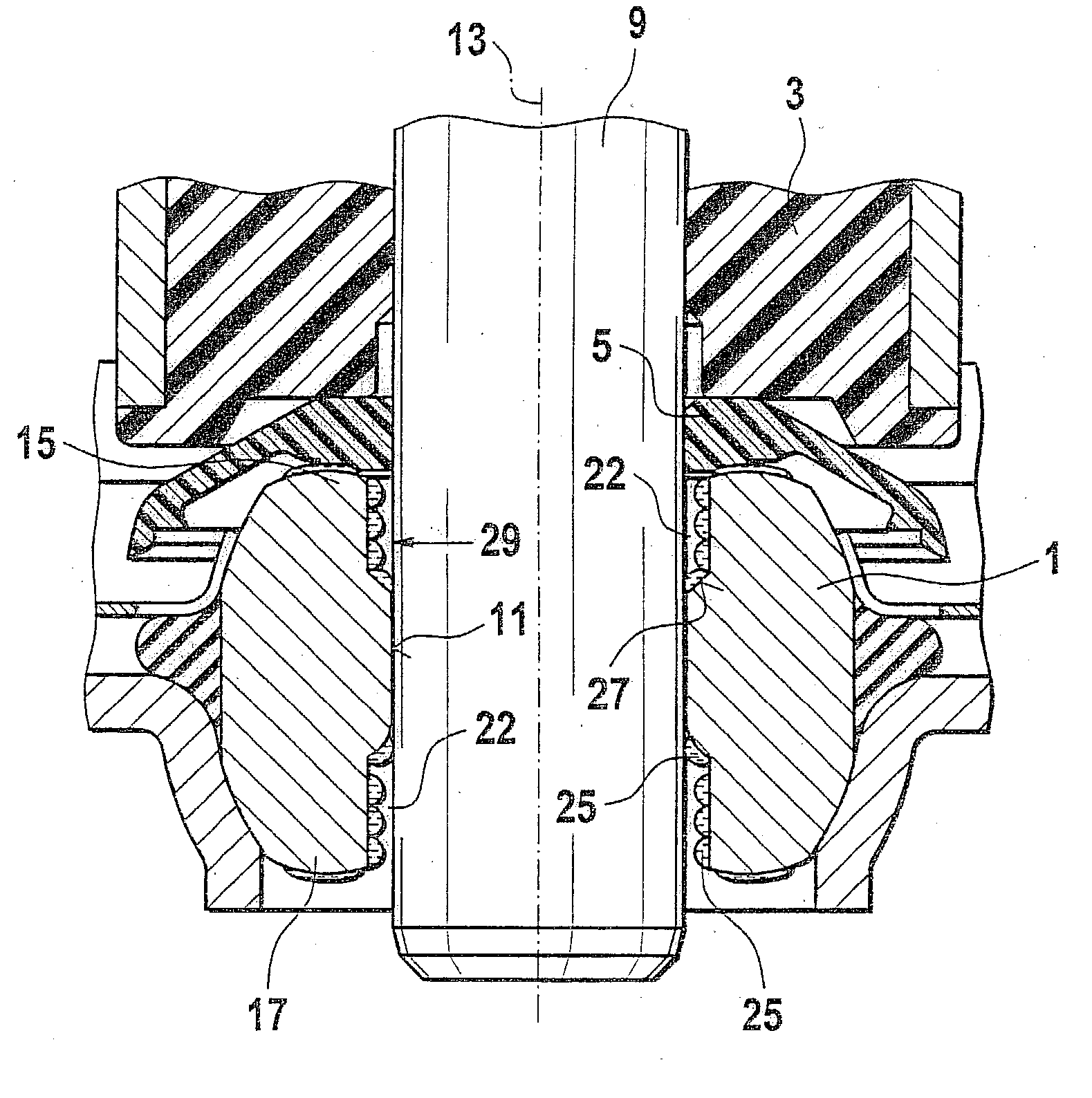
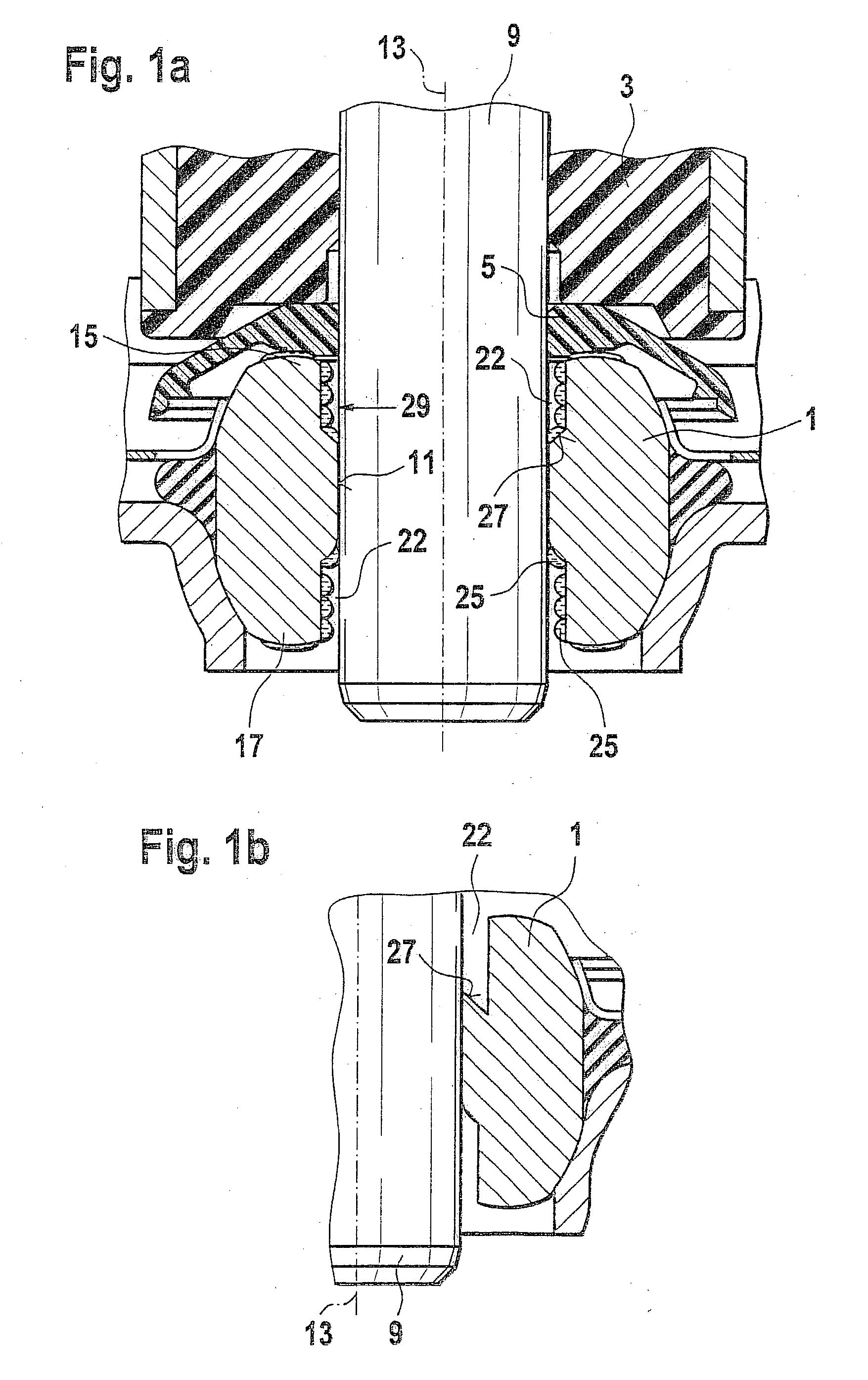
[0009] FIG. 1a shows a slide bearing 1 embodied according to the invention, which is present in a component 3, for instance a crankcase or gearbox, an electrical machine, or an electrical drive system. For example, the slide bearing 1 can also be a ball bearing.

[0010] A fastening means 5 is for instance present, by which the slide bearing 1 is secured in the component 3. Other types of fastening are also possible.

[0011] A shaft 9 is supported in the slide bearing 1. The support of the shaft 9 in the slide bearing 1 is effected via the contact face or slide face, that is, a running face 11 between the shaft 9 and the slide bearing 1.

[0012] The shaft 9 and the slide bearing 1 have an axis of symmetry 13 in the axial direction.

[0013] The running face 11 of the slide bearing 1 is for instance disposed centrally in the axial direction. One hollow chamber 22 each is located between the shaft 9 and the slide bearing 1, beginning at a first outer axial end 15 of the slide bearing 1 and at a...


PUM


Abstract

In a slide bearing of the prior art, any lubricant present is lost at the two outer axial ends of the bearing. In a slide bearing (1) of the invention, there are hollow chambers (22) at both outer axial ends (15, 17), which by the capillary effect cause escaping lubricant (25) to be stored in the hollow chamber (22).

Description

PRIOR ART[0001] U.S. Pat. No. 6,049,983 shows a sintered slide bearing which has hollow chambers in the circumferential direction on both axial ends of the sintered slide bearing. However, these hollow chambers do not serve to store escaping lubricant. For that purpose, a hollow chamber is used which is present centrally in the sintered bearing and is bounded in both axial directions by a running face of the sintered slide bearing. Lubricant escaping from the outer side faces is no longer available for lubrication, and also soils other components.[0002] From Japanese Patent Disclosure JP 07067282 A1, an armature with a bearing is known, which when the rotor shaft is mounted has an indentation on the face end. The slow leakage of fluid from a bearing is prevented, however, especially by means of an additional, fluid-absorbing material.ADVANTAGES OF THE INVENTION[0003] The slide bearing of the invention having the definitive characteristics of claim 1 has the advantage over the prior ...

Claims


Application Information

Patent Timeline
Patent Type & Authority Applications(United States)
IPC IPC(8): F16C17/02F16C33/10F16C33/12F16C33/74
CPCF16C17/02F16C33/74F16C33/104F16C33/103F16C17/04
Inventor EWERT, ANDREASWIELAND, BERND
Owner ROBERT BOSCH GMBH
Why Eureka
Try Eureka