Integrated heat exchanger

a heat exchanger and heat exchanger technology, applied in the direction of lighting and heating apparatus, process and machine control, instruments, etc., can solve the problems of extremely deteriorating cooling ability of condenser 1, low engine revolution speed,

Inactive Publication Date: 2003-10-09
CALSONIC KANSEI CORP
View PDF0 Cites 16 Cited by
  • Summary
  • Abstract
  • Description
  • Claims
  • Application Information

AI Technical Summary

Benefits of technology

0019] Still further, the condenser and the radiator are disposed in such a positional relationship that the lower temperature side of the coolant of the condenser overlaps a part of the radiator tubes through which the cooling water does not flow when the automobile is in an idling state an

Problems solved by technology

However, when the engine is in an idling state, the revolution speed of the engine is low.
At this time, if heat is transmitted from the

Method used


Image

  • Integrated heat exchanger
  • Integrated heat exchanger
  • Integrated heat exchanger

Examples


Embodiment Construction

.

[0028] By reference to the accompanying drawings, an embodiment of the present invention will be described in detail hereinbelow.

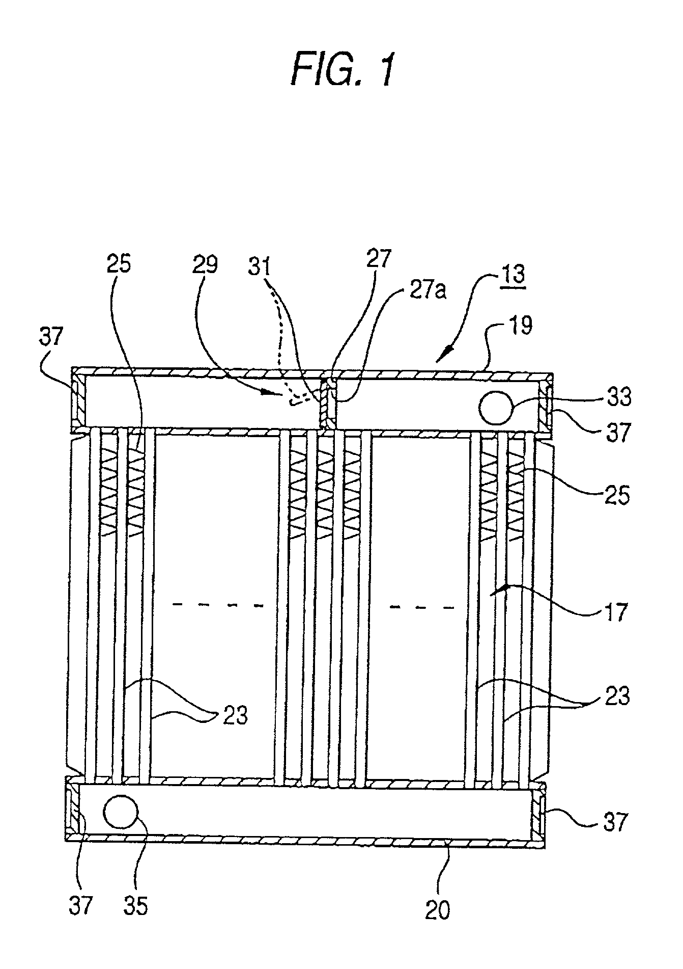
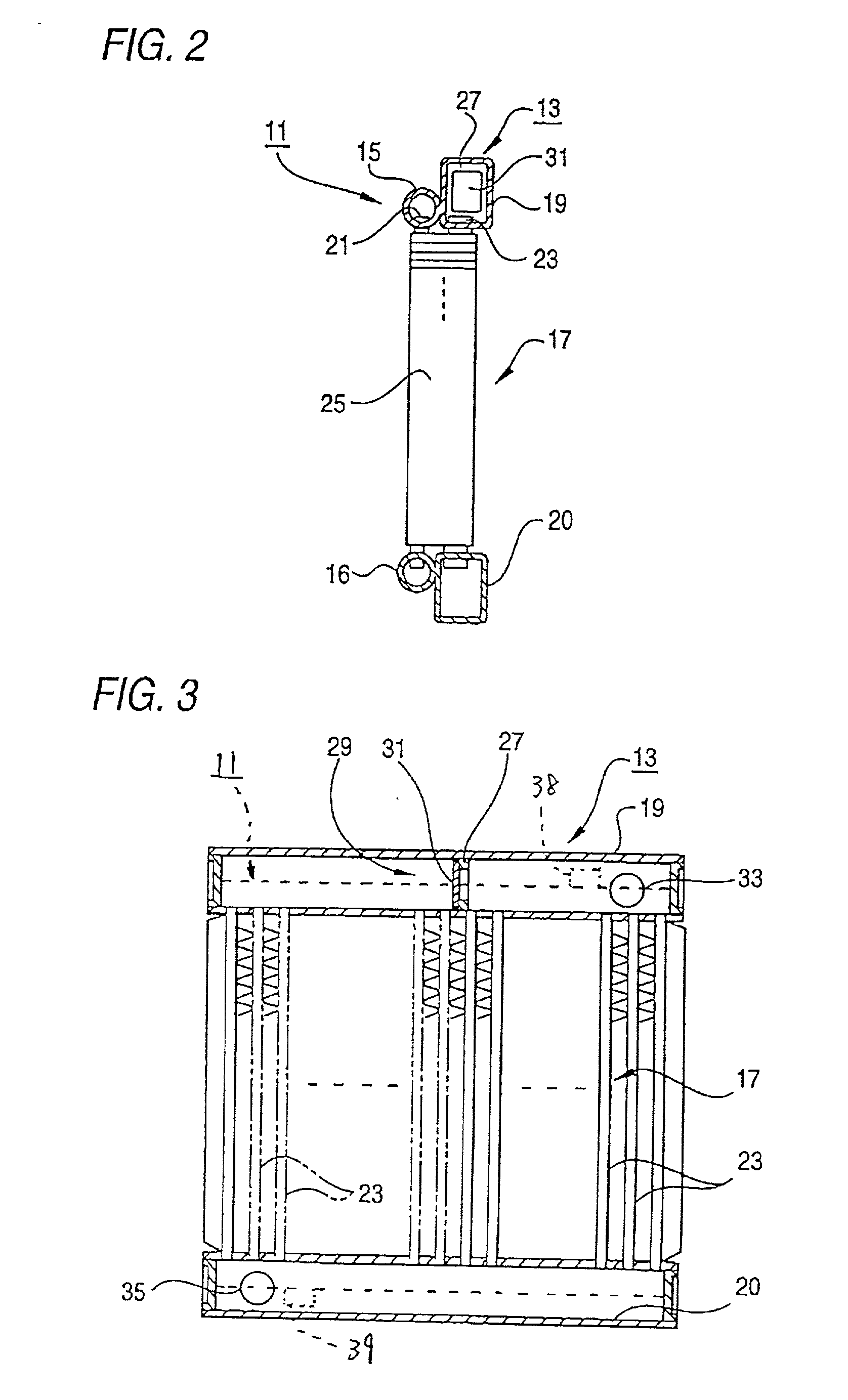
[0029] FIG. 1 is a longitudinal cross-sectional view showing a radiator of a heat exchanger shown in FIG. 2, and FIG. 2 shows an integrated heat exchanger according to the present invention.

[0030] In the integrated heat exchanger shown in FIG. 2, a condenser 11 is provided in front of a radiator 13.

[0031] The condenser 11 comprises a pair of condenser tanks 15, 16 which are spaced a given distance apart from and are opposite to each other, and a core 17 formed between the condenser tanks 15, 16.

[0032] The radiator 13 comprises a pair of radiator tanks 19, 20 which are spaced a given distance apart from and are opposite to each other, and the core 17 formed between the radiator tanks 19, 20.

[0033] Tubes 21 for use with the condenser and tubes 23 for use with the radiator are provided in the core 17.

[0034] Wide corrugated fins 25 are brazed so as to extend ...


PUM


Abstract

An integrated heat exchanger which includes a radiator adjoining a condenser and shares corrugated fins disposed in a core formed between the radiator and the condenser, the heat exchanger including a partition for dividing the inside of a tank of the radiator into which cooling water flows; and opening/closing means which is disposed in the partition so as to open when the temperature of the cooling water reaches a given temperature or more, as well as to close when the temperature of the cooling water is less than the given temperature.

Description

[0001] This is a Continuation-In-Part of application Ser. No. 09 / 015,783, filed on Jan. 29, 1998, which is incorporated herein by reference.[0002] 1. Field of the Invention[0003] The present invention relates to an integrated heat exchanger comprising a radiator adjoining a condenser, and corrugated fins which are provided in a core formed between the radiator and the condenser and are shared between them.[0004] 2. Description of the Related Art[0005] There has recently been developed a so-called integrated heat exchanger comprising a condenser for cooling purposes which is joined to the front surface of the radiator. FIG. 6 shows an integrated heat exchanger of this type, wherein a condenser 1 is provided in front of a radiator 2.[0006] The condenser 1 comprises a pair of condenser tanks 3, 3 which are spaced a given distance away from and are opposite to each other and a core 4 formed between the pair of condenser tanks 3, 3. The radiator 2 comprises a pair of radiator tanks 5, 5 ...

Claims


Application Information

Patent Timeline
IPC IPC(8): F28D1/04F28F9/02F28F27/02
CPCF28D1/0435F28D2021/0084F28F2215/02F28F9/0202F28F27/02F28D2021/0094
Inventor MURAMOTO, HIRONORI
Owner CALSONIC KANSEI CORP
Why Eureka
Try Eureka