Combined hardware and software architecture for remote monitoring

a software architecture and hardware technology, applied in the field of distributed communications systems, can solve problems such as equipment shut down, significant adverse effects on productivity and efficiency, and equipment damage,

Inactive Publication Date: 2003-10-23
M2M MATRIX INC
View PDF5 Cites 82 Cited by
  • Summary
  • Abstract
  • Description
  • Claims
  • Application Information

AI Technical Summary

Problems solved by technology

Many industries, including oil and gas, are faced with the problem of monitoring production facilities and other equipment which are distributed over a wide geographic area.
This can have significant adverse effects on productivity and efficiency.
Further, alarms resulting from operational upsets may not be noticed until the next visit during which time equipment may be shut down, or may be damaged.
In particular, the wireless connections are generally slow and range limited.
These connections result in bandwidth restrictions as well as timing concerns.
This communications approach also provides little, if any, capability to interactively query or reconfigure the remote equipment.
The data viewing service provided by the server also suffers from a bandwidth and performance limitation.
The formatted reports and graphics are then transmitted to the users monitor or computer, either requiring very high bandwidth or providing very poor performance.
Much of this performance problem is due to the need to transmit the graphical displays which are data intense.
A further problem with the typical prior art approach is that at least some of the architecture components are proprietary.
This limits the number of potential sources of supply, driving up costs, and incurring the risk that a sole source vendor may stop supporting a needed product.

Method used


Image

  • Combined hardware and software architecture for remote monitoring
  • Combined hardware and software architecture for remote monitoring
  • Combined hardware and software architecture for remote monitoring

Examples


Embodiment Construction

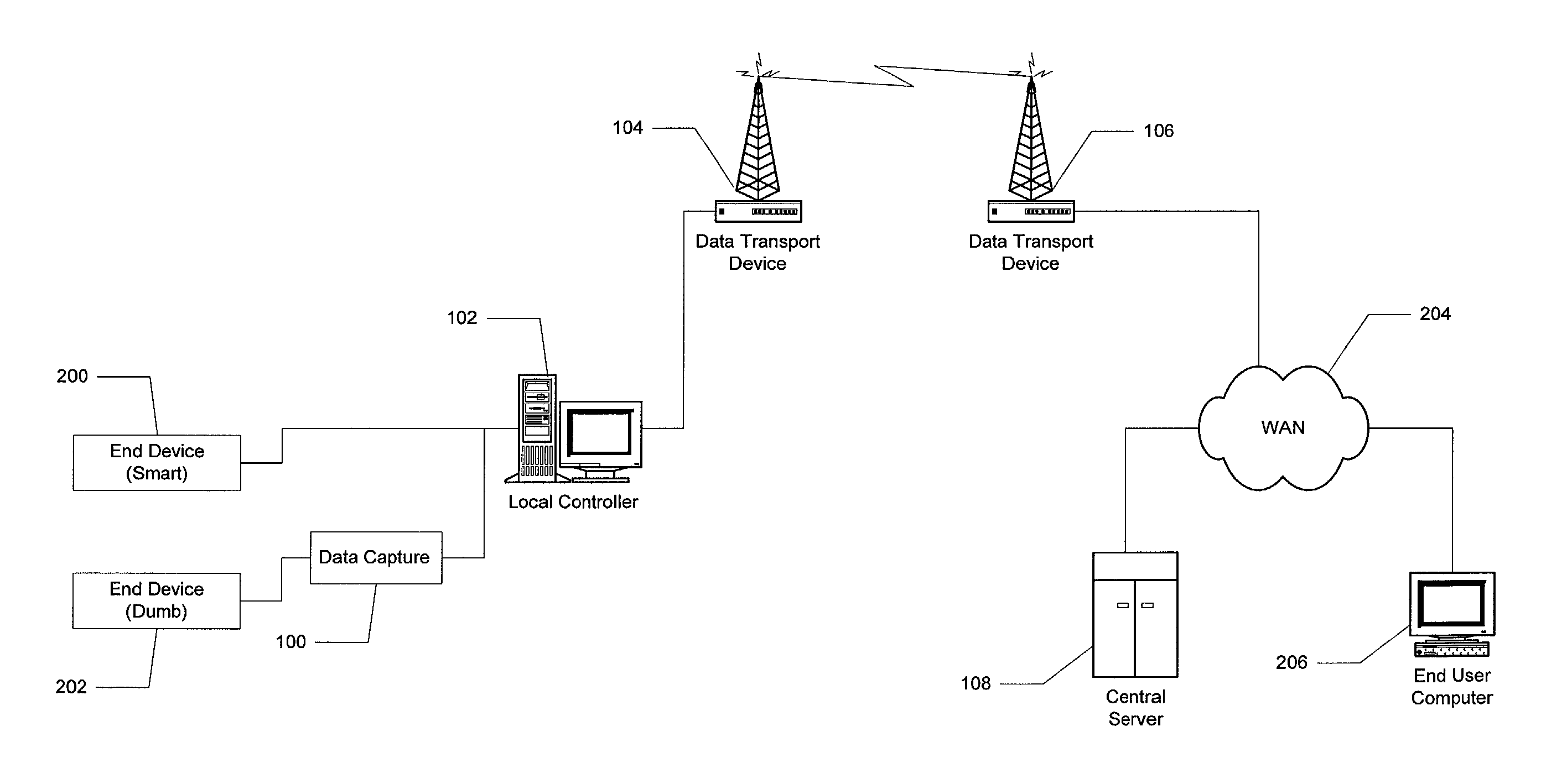
[0039] The disclosed invention is described below with reference to the accompanying figures in which like reference numbers designate like parts. Generally, numbers in the 200's refer to prior art elements or elements in the surrounding environment while numbers in the 100's refer to elements of the invention. Numbers in the 300's are used to designate processing steps implemented by the invention.

[0040] Overview

[0041] The present invention is a system for remote monitoring of equipment and / or processes. A typical application would be monitoring oil and gas production wells. These wells are typically distributed across oil or gas fields spanning large geographic areas. A single production office may have responsibility for many fields and hundreds of wells spread across hundreds of square miles. Each of these wells may have in place smart end devices, such as meters and valves, which are capable of communicating with a microcomputer or the wells can be equipped with data capture de...


PUM


Abstract

A system for the monitoring of remote equipment or processes such as oil and gas wells. The system utilizes a local controller at each site which transmits data to a central server over a wide area network. Preferably, the local controller will be connected to the wide area network via a wireless radio frequency connection. The central server then provides the stored data to users via served web pages or custom software viewable on any compatible computer attached to the network. The users of the system can also enter data values into web pages on the viewing computer to be transferred through the system to the local controller to alter its operation or that of the equipment to which it is attached.

Description

[0001] None[0002] Not Applicable[0003] 1. Field of the Invention[0004] The present invention relates to the field of distributed communications systems and specifically to such systems used to monitor remote, distributed equipment or production systems.[0005] 2. Background Information[0006] Many industries, including oil and gas, are faced with the problem of monitoring production facilities and other equipment which are distributed over a wide geographic area. In the case of oil and gas well production, a single production office may have responsibility for many fields and hundreds of wells spread across hundreds of square miles. The most common approach to the monitoring problem is to have personnel physically visit each site periodically, as often as daily, to adjust equipment settings and record data which are then used by the production office to modify operational parameters at each well. Because of the travel time involved, the production office is often working with data tha...

Claims


Application Information

Patent Timeline
Patent Type & Authority Applications(United States)
IPC IPC(8): E21B47/00H04L29/06H04L29/08
CPCE21B47/00G05B2219/31457H04L29/06H04L67/025H04L69/329H04L67/12H04L67/02H04L67/10H04L67/04H04L9/40
Inventor CASTLEBURY, MICHAEL J.LUKE, FOREST W.FAULHABER, MATTHEW J.
Owner M2M MATRIX INC
Why Eureka
Try Eureka