Clock control circuit and method

a control circuit and clock technology, applied in the direction of generating/distributing signals, pulse techniques, instruments, etc., can solve the problem of difficult to generate correctly a signal of a desired phas

Inactive Publication Date: 2003-10-23
RENESAS ELECTRONICS CORP
View PDF9 Cites 33 Cited by
  • Summary
  • Abstract
  • Description
  • Claims
  • Application Information

AI Technical Summary

Benefits of technology

[0006] Accordingly, it is an object of the present invention to provide a clock control circuit and method for precisely generating output clocks of a desired phase difference with respect to an input clock.

Problems solved by technology

This makes it difficult to generate correctly a signal of a desired phase.

Method used


Image

  • Clock control circuit and method
  • Clock control circuit and method
  • Clock control circuit and method

Examples


first embodiment

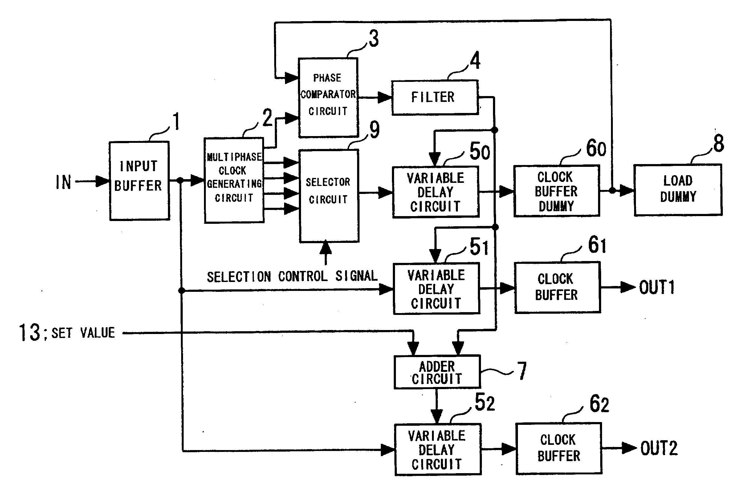
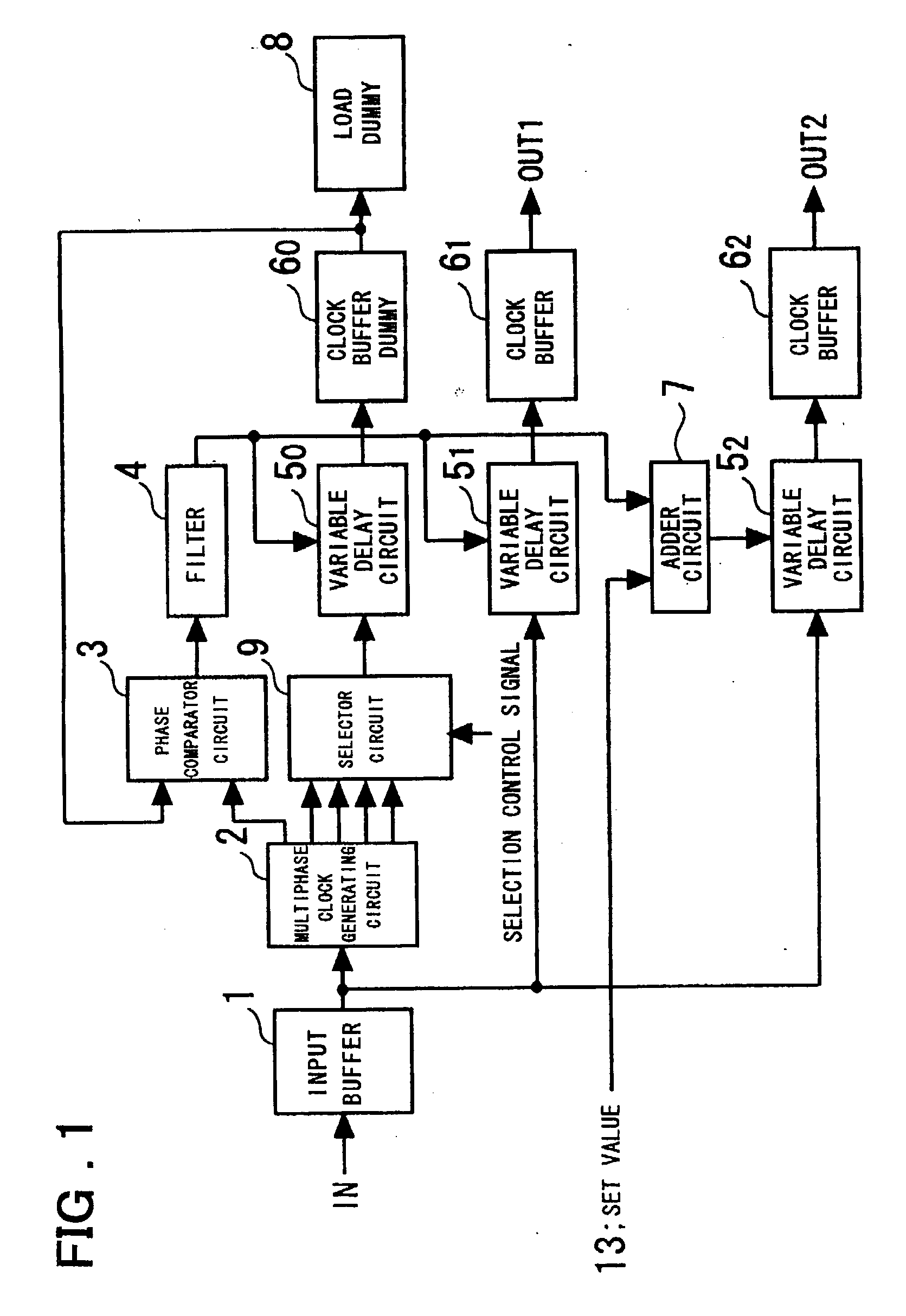
[0068] The operation of the invention shown in FIG. 1 will now be described.

[0069] The selector circuit 9 selects a clock (a clock having an ith phase), which has a described phase relationship with respect to the clock supplied to the phase comparator circuit 3, from among the multiphase clocks output from the multiphase clock generating circuit 2. The phase comparator circuit 3 is controlled in such a manner that the delay time of the variable delay circuit 5.sub.0 and clock buffer dummy 6.sub.0 will become equal to this phase difference, the output OUT1 delivers a first clock signal having a desired phase difference with respect to the input clock, and the output OUT2 delivers a second clock signal having a desired phase difference with respect to the first clock signal output from the output OUT1. The selection made by the selector circuit 9 may be in response to a selection control signal from a CPU (not shown) or a selection control signal that is applied externally. For examp...

second embodiment

[0090] As for the generation of the phase difference, several arrangements are applicable in addition to the above-described arrangement of the multiphase clock generating circuit and selector circuit. the invention having an interpolator-based phase-difference generating circuit will be described next.

[0091] FIG. 8 is a block diagram illustrating the structure of a second embodiment of the present invention.

[0092] As shown in FIG. 8, a clock control circuit in accordance with the second embodiment of the invention comprises: a phase-difference generating circuit 10, to which the output signal of the input buffer 1 is provided, for outputting first and second signals a, b obtained by delaying the output signal of input buffer 1 by a predetermined phase difference on the basis of a phase decision information 14 received; the variable delay circuit 5.sub.0 for delaying the second output b of the phase-difference generating circuit 10; the clock buffer dummy 6.sub.0 for driving the out...

third embodiment

[0115] FIG. 14 is a diagram showing the structure of the phase-difference generating circuit 10A (see FIGS. 12, 13) in the present invention. As shown in FIG. 14, the phase-difference generating circuit 10A comprises the frequency divider circuit 101 for frequency-dividing an input clock by eight; the first D-type flip-flop 102.sub.1 for sampling the frequency-divided clock by the frequency divider circuit 101 with the input clock; the second D-type flip-flop 102.sub.2 for sampling the output A of the first D-type flip-flop 102.sub.1 with the input clock; the first interpolator 103.sub.1, to which outputs A, B of the first and second flip-flops 102.sub.1, 102.sub.2 are input, for producing an output signal having a delay time decided by a time obtained by performing an interior division of the timing difference between the two outputs by a first interior-division ratio on the basis of a control signal (control code) S[0:31] constituting the phase decision information 14; a third D-t...


PUM


Abstract

A clock control circuit includes a multiphase clock generating circuit receiving an output signal of a input buffer for generating multiphase clocks; a selector circuit receiving multiphase clocks output from the multiphase clock generating circuit for selecting one of the multiphase clocks; a first variable delay circuit for delaying the output of the selector circuit; a clock buffer dummy receiving the output signal of the variable delay circuit; a phase comparator circuit for detecting a phase difference between an output from the multiphase clock generating circuit and an output of the clock buffer dummy; and a filter for smoothing the output of the phase comparator circuit. The first variable delay circuit has its delay time varied by the output of the filter. The clock control circuit further includes a second variable delay circuit, receiving the output signal of the input buffer, having its delay time varied by the output of the filter; an adder circuit for adding the filter output and an input set value; a third variable delay circuit, receiving the output signal of the input buffer, having its delay time varied by the output of the adder circuit; and clock buffers receiving output signals of respective ones of the second and third variable delay circuits.

Description

[0001] This invention relates to a clock control circuit and to a clock control method.[0002] An arrangement using a DLL (Delayed-Locked Loop) of the kind shown in FIG. 18 is known as a circuit that generates a signal having a prescribed phase with respect to an input signal. With regard to the arrangement shown in FIG. 18, see Reference 1 (ISSCC 1997 pp. 332-333, S. Sidiropoulos and Mark Horowitz et al., "A Semi-Digital DLL with Unlimited Phase Shift Capability and 0.08-400 MHz Operating Range").[0003] As shown in FIG. 18, the DLL has an input buffer 11, a voltage-controlled delay line 14, a phase comparator 12 for detecting a phase difference between an output signal of the voltage-controlled delay line 14 and an output signal of the input buffer 11, and a filter 13 for smoothing a phase-difference detection signal output from the phase comparator 12. The voltage-controlled delay line 14 comprises a plurality of cascade-connected buffers. The phase comparator 12 is constituted by,...

Claims


Application Information

Patent Timeline
Patent Type & Authority Applications(United States)
IPC IPC(8): G06F1/06G06F1/10H03K5/00H03K5/13H03K5/15H03L7/00H03L7/081
CPCG06F1/06G06F1/10H03L7/0814H03L7/0812H03L7/0805H03L7/0818H03L7/00
Inventor SAEKI, TAKANORI
Owner RENESAS ELECTRONICS CORP
Why Eureka
Try Eureka