

Joining of structural members by friction plug welding
a technology of friction plug welding and structural members, which is applied in the direction of soldering apparatus, manufacturing tools, auxillary welding devices, etc., can solve the problems of labor, time and materials, and the difficulty of simultaneously supporting and secure the inside and outside of the dome and cylinder, and achieves cost-effectiveness.
- Summary
- Abstract
- Description
- Claims
- Application Information
AI Technical Summary
Benefits of technology
Problems solved by technology
Method used
Image

Examples
Embodiment Construction
Background of Invention
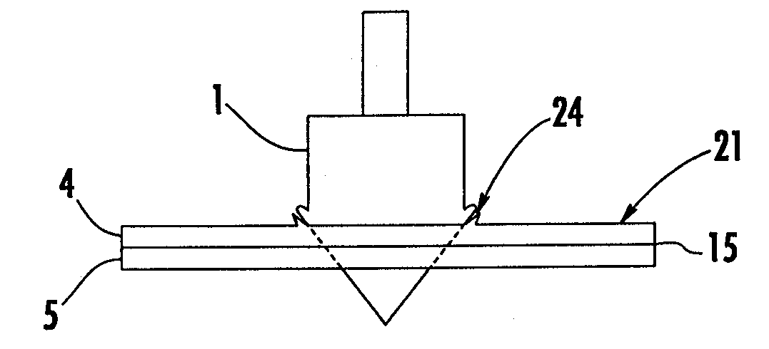
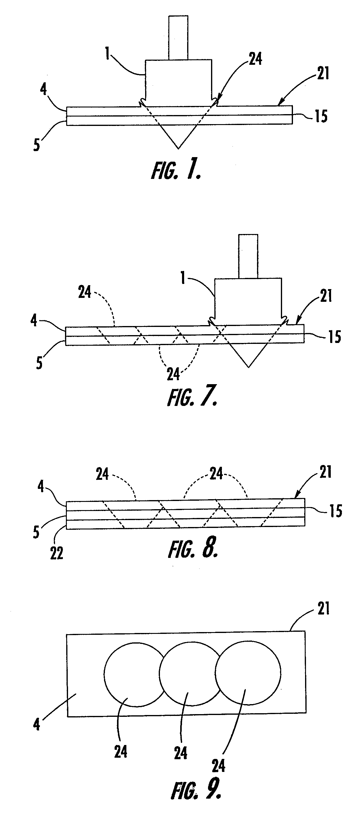
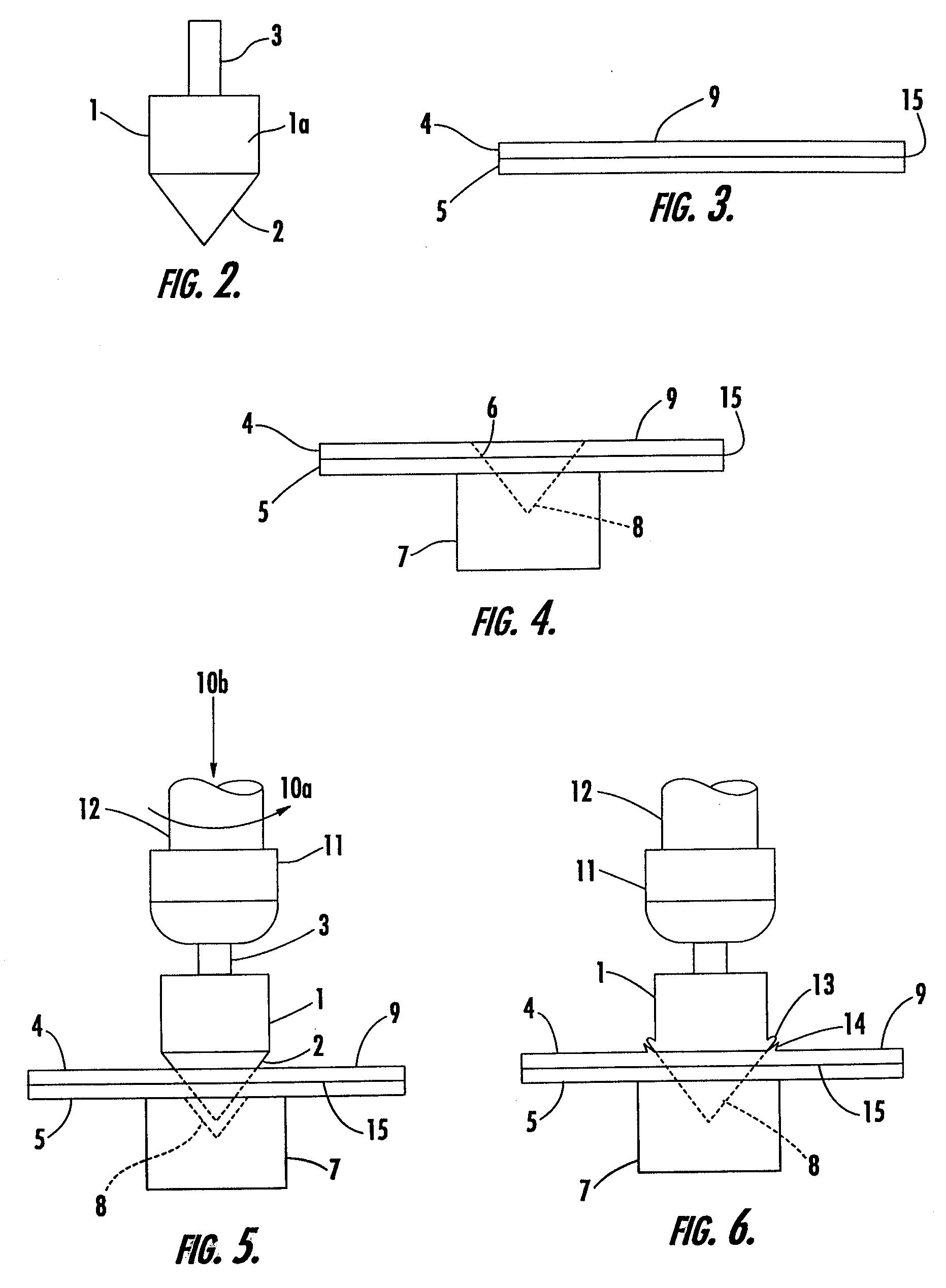
[0001] FIELD OF THE INVENTION. This invention relates to friction welding and, more specifically, to the joining of structural members by friction plug welding.
[0002] BACKGROUND OF THE INVENTION. Structural assemblies, such as those in the aerospace industry, are often constructed by joining structural members together. The structural members can be joined to one another by welding along the joint interface between the members or using fasteners, such as rivets, screws, or bolts. Oftentimes it is necessary to join structural members that have complex geometries or configurations that complicate the joining process. For example, when joining structural members having curvilinear configurations, it can be difficult to position and secure the members relative to one another while preventing gapping and maintaining the joint interface free of obstruction. Similarly, some structural members have configurations that restrict access to the joint interface between the...
PUM
| Property | Measurement | Unit |
|---|---|---|
| stress concentrations | aaaaa | aaaaa |
| grain sizes | aaaaa | aaaaa |
| grain sizes | aaaaa | aaaaa |
Abstract
Description
Claims
Application Information