Ultrasonic assisted processes

a technology of ultrasonic and assisted processes, applied in the direction of mechanical vibration separation, manufacturing tools, blood vessels, etc., can solve problems such as pressure drop, and achieve the effect of reducing inflation and deflation tim

Inactive Publication Date: 2003-10-30
BOSTON SCI SCIMED INC
View PDF34 Cites 52 Cited by
  • Summary
  • Abstract
  • Description
  • Claims
  • Application Information

AI Technical Summary

Benefits of technology

0029] During dilitation procedures, ultrasonic energy is applied to the lumen of the...

Problems solved by technology

A large ultrasonic amplitude will ...

Method used


Image

  • Ultrasonic assisted processes
  • Ultrasonic assisted processes
  • Ultrasonic assisted processes

Examples


Embodiment Construction

is hereafter described with specific reference being made to the following drawings.

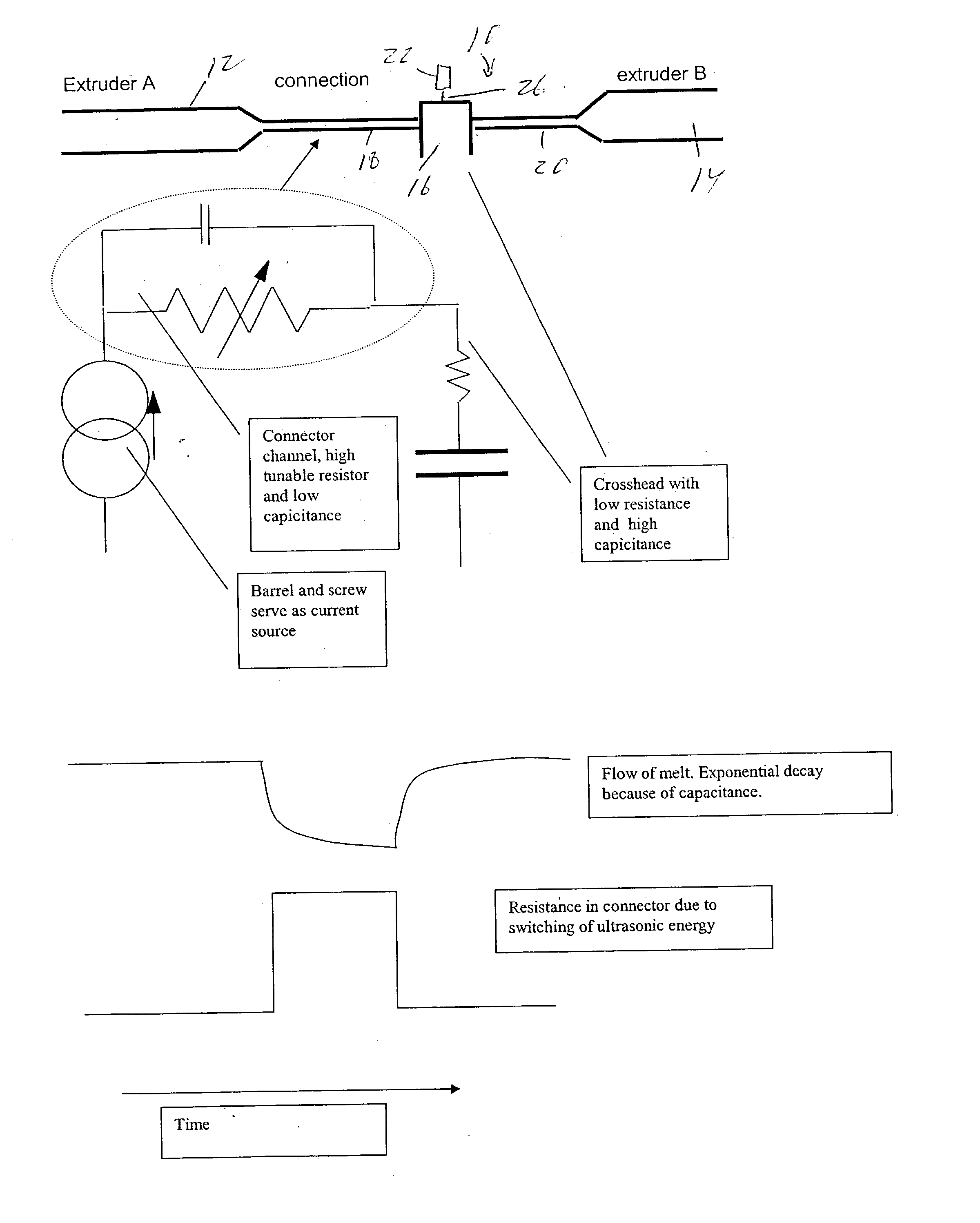
[0034] FIG. 1 is a diagrammatic view of an embodiment of the invention wherein a pair of extruders are linked together for coextrusion of a polymer melt through a cross head.

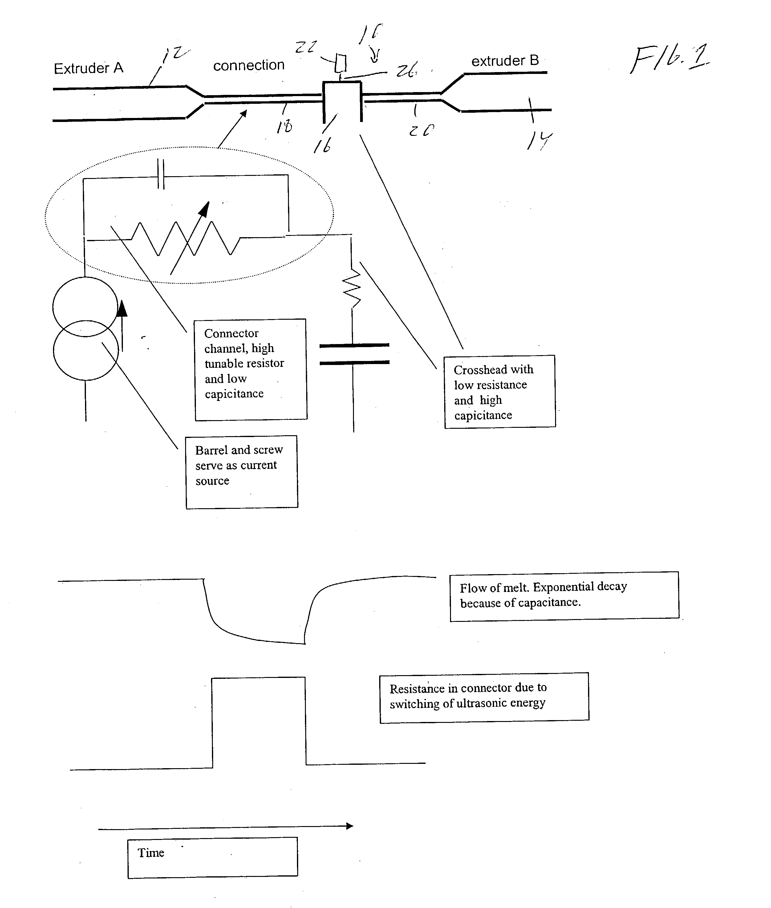
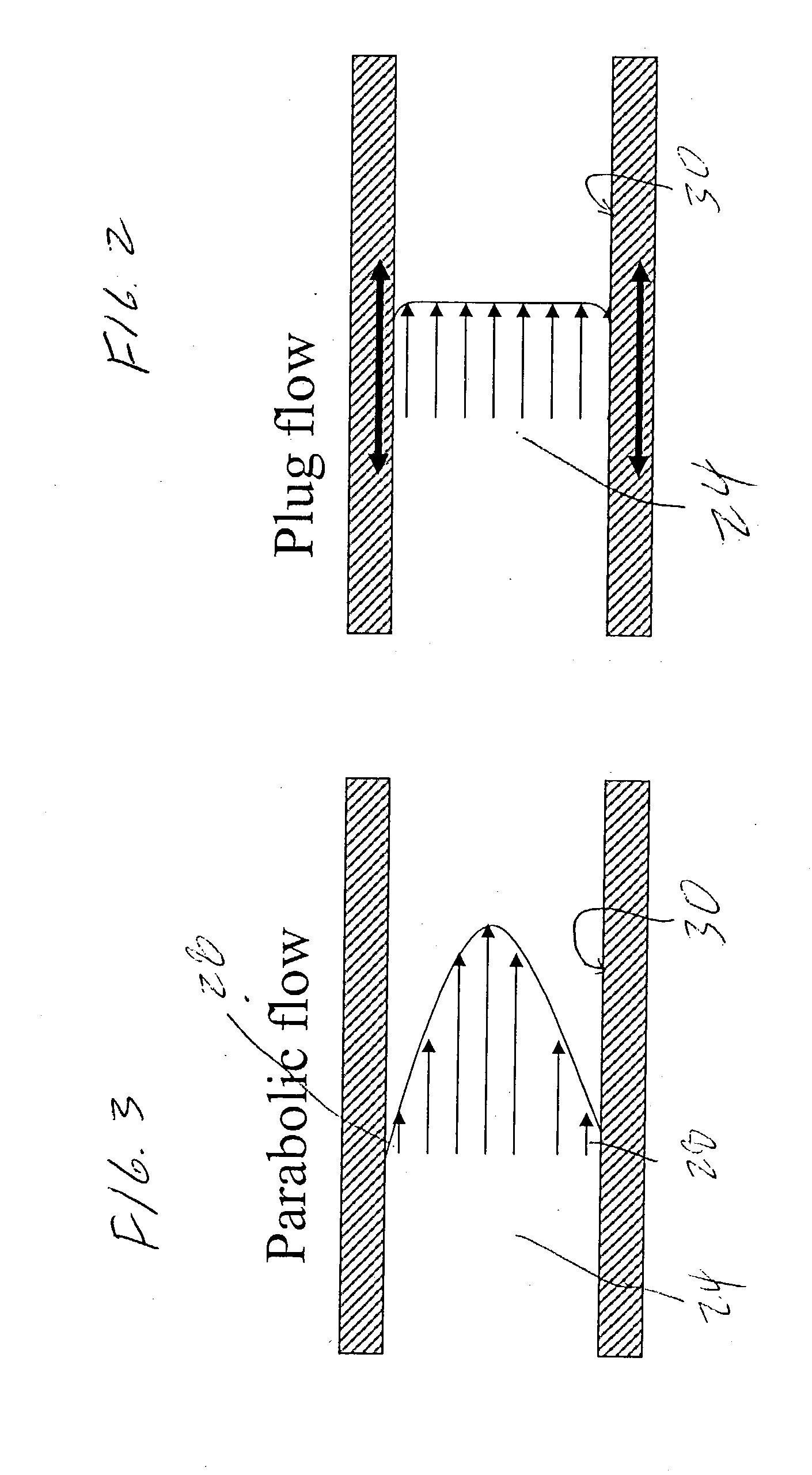
[0035] FIG. 2 is a side view of a melt flow seen flowing through a portion of an extruder as desired according to an aspect of the invention.

[0036] FIG. 3 is a PRIOR ART side view of a melt flow seen flowing through a portion of an extruder as may occur in a prior art extruder process.

[0037] FIG. 4 is a diagrammatic view of an embodiment of the invention wherein a pair of extruders are linked together for coextrusion of a polymer melt through a cross head.

[0038] FIG. 5 is a example of a modulated ultrasonic wave formed according to an embodiment of the invention.

[0039] FIG. 6 is a diagrammatic view of an embodiment of the invention wherein a pair of extruders are linked together for coextrusion of a polymer melt through a cross h...


PUM

PropertyMeasurementUnit
Timeaaaaaaaaaa
Flow rateaaaaaaaaaa
Frequencyaaaaaaaaaa

Abstract

Method and apparatus for applying ultrasonic energy to a variety of manufacturing processes, particularly for producing an extrudate product from an extruder wherein one or more ultrasonic transducers are utilized to uniformly ultrasonically vibrate at least a portion of an extruder assembly.

Description

[0001] Not Applicable[0002] Not Applicable[0003] Parison tubes such as may be used in the manufacture of medical devices, such as catheters and balloons among others, are typically made by an extrusion process. An extrusion process may involve the melting of polymer pellets wherein the melted polymer is pushed through a tip and die combination to form a generally tubular shape. By pulling the tube at a higher speed than it is pushed out of the tip and die the diameter of the tube is reduced. This reduction is typically expressed as a draw down ratio. During the draw down process the polymer is oriented in the axial direction. From the resulting extrudate parison, balloons, for example may be subsequently formed. The higher the orientation in the extrudated parison, the higher the strength of the balloon.[0004] Polymer melts have a relatively high viscosity and in order to reduce viscosity the temperature of the polymer melt is raised during the extrusion process. During extrusion at...

Claims


Application Information

Patent Timeline
IPC IPC(8): A61F2/06A61F2/90B23K26/14B23K26/16B29C35/02B29C41/08B29C48/21B29C48/49B29C65/16
CPCA61F2/91B23K26/1417B23K26/16B29C35/0261B29C41/08B29C47/0023B29L2031/7542B29C47/062B29C47/56B29C65/16B29K2995/0003B29K2995/0046B29C47/0071B23K26/146B29C48/09B29C48/14B29C48/19B29C48/49B29C48/21
Inventor WEBER, JANDEVENS, DOUGLAS A. JR.
Owner BOSTON SCI SCIMED INC
Why Eureka
Try Eureka