
Avalanche photodiode controller circuit for fiber optics transceiver

Inactive Publication Date: 2003-11-13
II VI DELAWARE INC
View PDF17 Cites 100 Cited by
  • Summary
  • Abstract
  • Description
  • Claims
  • Application Information

AI Technical Summary

Problems solved by technology

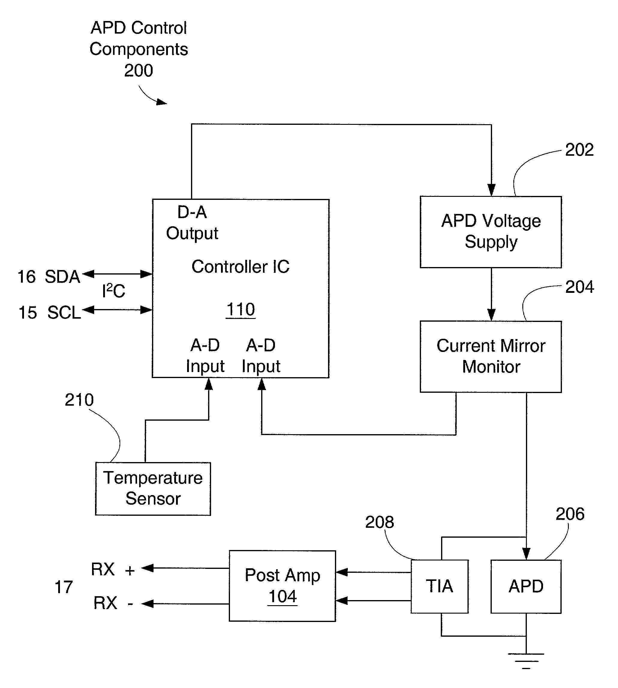
Unfortunately, avalanche voltages vary from one device to the next, and they also vary as a function of the temperature of the particular device.
Under high-volume manufacturing conditions, however, this approach is not desirable because each receiver / transceiver has to be manually tuned to account for variations among thermistors and photodiodes.
This approach, however, is generally not feasible for pluggable optoelectronic transceivers / receivers because temperature controllers are typically too big to fit within such devices.
As pluggable optoelectronic transceivers / transmitters become more and more compact, the use of temperature controller in these devices is becoming less and less feasible.

Method used


Image

  • Avalanche photodiode controller circuit for fiber optics transceiver
  • Avalanche photodiode controller circuit for fiber optics transceiver
  • Avalanche photodiode controller circuit for fiber optics transceiver

Examples


Embodiment Construction

[0027] Preferred embodiments of the invention are described below. In the interest of clarity, not all features of an actual implementation are described. It will be appreciated that in the development of any such embodiment, numerous implementation-specific decisions must be made to achieve the developers' specific goals, such as compliance with system-related and business-related constraints, which will vary from one implementation to another. Moreover, it will be appreciated that such a development effort might be complex and time-consuming, but would nevertheless be a routine undertaking for those of ordinary skill in the art having the benefit of this disclosure.

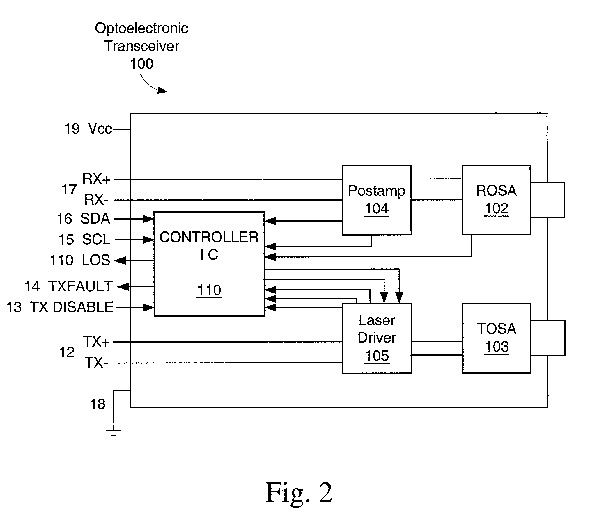
[0028] A transceiver 100 based on the present invention is shown in FIGS. 2 and 3. The transceiver 100 contains a Receiver Optical Subassembly (ROSA) 102 and Transmitter Optical Subassembly (TOSA) 103 along with associated post-amplifier 104 and laser driver 105 integrated circuits that communicate the high speed electr...


PUM


Abstract

A controller for controlling the reverse-bias voltage of an avalanche photodiode in a transceiver or receiver. The controller includes memory for storing information related to the avalanche photodiode, and analog to digital conversion circuitry for receiving an analog signal corresponding to the temperature of the avalanche photodiode, converting the received analog signal into a digital value, and storing the digital value in a predefined location within the memory. Control circuitry in the controller controls the operation of the avalanche photodiode in accordance with the digital value corresponding to the temperature of the avalanche photodiode and a temperature lookup table stored in the memory. A serial interface is provided to enable a host device to read from and write to locations within the memory. The invention is also implemented as a method for controlling the reverse-bias voltage of an avalanche photodiode in a transceiver or receiver and a method for calibrating a transceiver or receiver having an avalanche photodiode.

Description

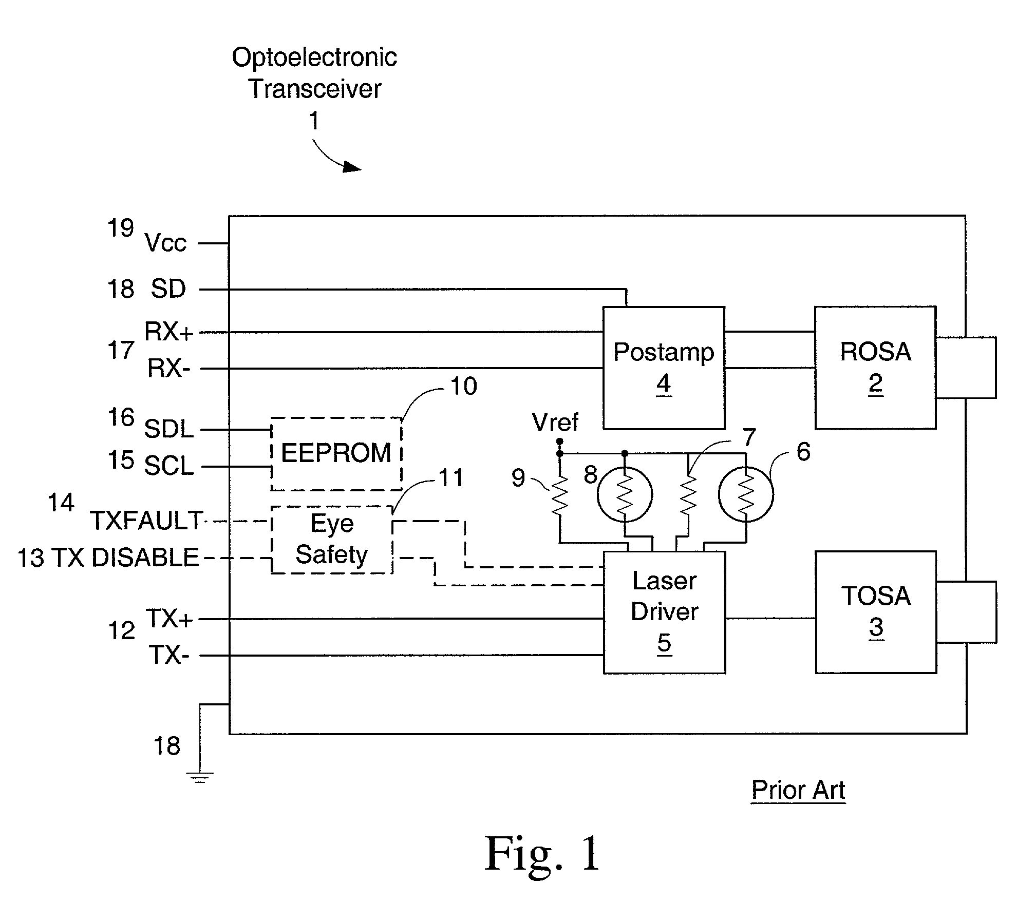
[0001] The present application claims priority to United States Provisional Patent Application filed Feb. 12, 2002, bearing attorney docket number 9775-0073-888, which is incorporated herein by reference.[0002] This application is related to copending U.S. patent application Ser. No. 09 / 777,917 filed Feb. 5, 2001, which is incorporated herein by reference.[0003] The present invention relates generally to the field of fiber optic transceivers. More particularly, the invention relates to optoelectronic transceivers and optoelectronic receivers having avalanche photodiodes and to circuits for controlling avalanche photodiodes in optoelectronic transceivers and optoelectronic receivers.BACKGROUND OF INVENTION[0004] FIG. 1 shows a schematic representation of the essential features of a typical prior-art fiber optic transceiver. The main circuit 1 contains at a minimum transmit and receive circuit paths and power 19 and ground connections 18. The receiver circuit typically consists of a R...

Claims


Application Information

Patent Timeline
IPC IPC(8): H04B10/158
CPCH04B10/6931H04B10/6911
Inventor STEWART, JAMESHO, ANTHONYHOFMEISTER, RUDOLF J.DOUMA, DARIN JAMESHOSKING, STEPHEN G.WEBER, ANDREASPRICE, JEFFREY BRYANT
Owner II VI DELAWARE INC
Learn More