Drill pipe connecting and disconnecting apparatus

a technology of connecting and disconnecting equipment and drilling pipes, which is applied in the direction of drilling pipes, manufacturing tools, and well accessories, etc., can solve the problems of inherently dangerous operation of tongs and pipes, inability to operate properly, and inability to meet the requirements of the job,

Inactive Publication Date: 2003-12-04
FORUM US
View PDF25 Cites 114 Cited by
  • Summary
  • Abstract
  • Description
  • Claims
  • Application Information

AI Technical Summary

Benefits of technology

[0015] Another object of the invention is to provide a remotely controlled tool joint connecting and disconnecting tool which requires no horizontal movement along the drilling platform floor for saving valuable space on the platform floor.
[0016] Another object of the invention is to provide a remotely controlled hydraulically powered drill pipe connecting and disconnecting tool which is installed without being horizontally moveable with respect to the well axis and requires no manual manipulation of equipment at the well enter when tool joints are being connected or disconnected.

Problems solved by technology

Operating the tongs and pipes is inherently dangerous, because a rig employee or "roughneck" must physically handle the powerful equipment near the drill pipe.
Accidents have been common with loss of fingers, hands, etc.
The prior procedures and equipment described above are inherently dangerous to roughnecks working to make-up and break apart and disconnect drill pipe connections.
The Iron Roughneck has solved some of the safety problems of manual tongs and spinners, yet problems still exist.
The first is that horizontal movement on the rig floor takes up limited horizontal space.
All such manual operations at the well center create the opportunity for accidents to well operating personnel.

Method used


Image

  • Drill pipe connecting and disconnecting apparatus
  • Drill pipe connecting and disconnecting apparatus
  • Drill pipe connecting and disconnecting apparatus

Examples


Embodiment Construction

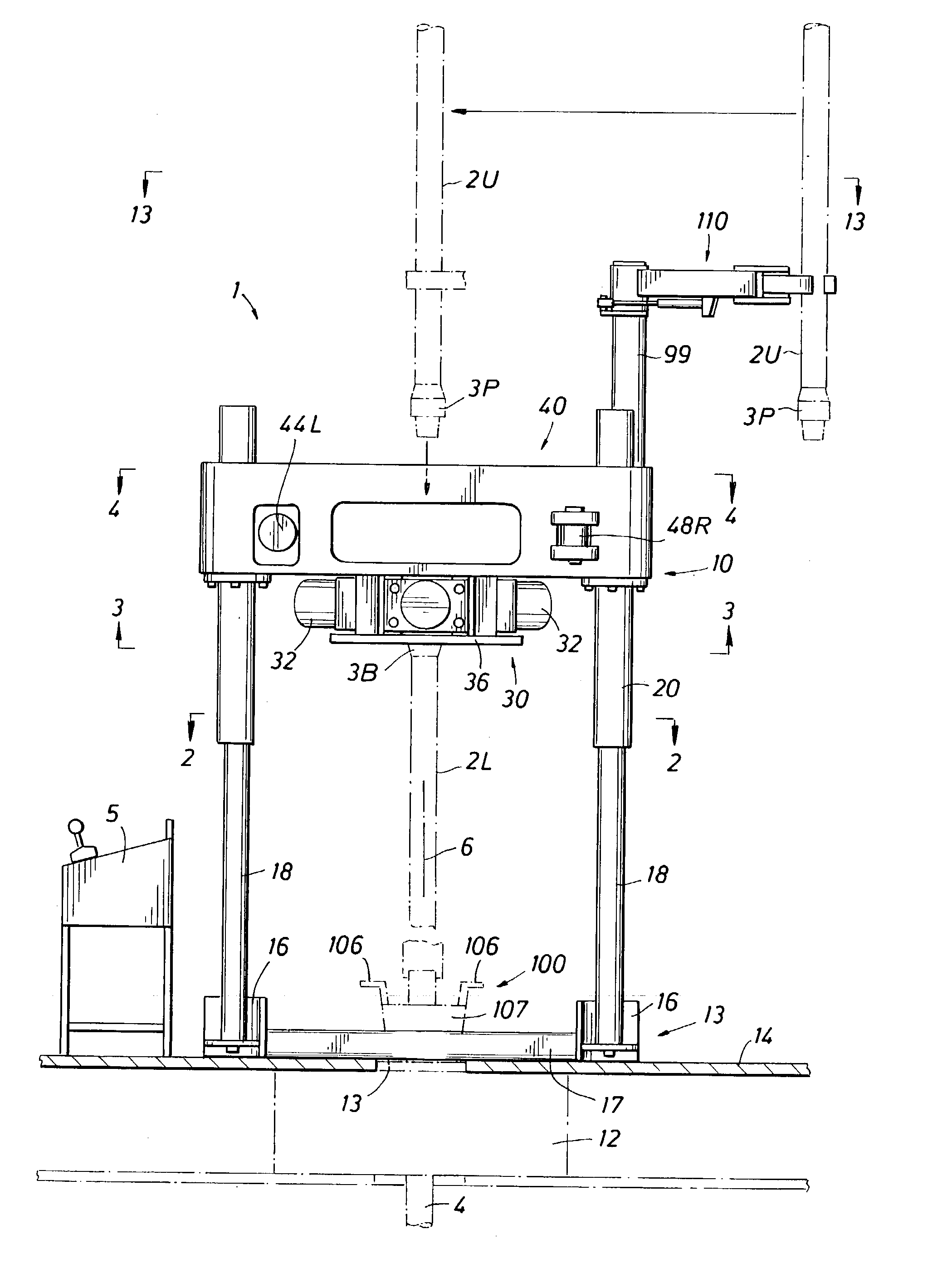
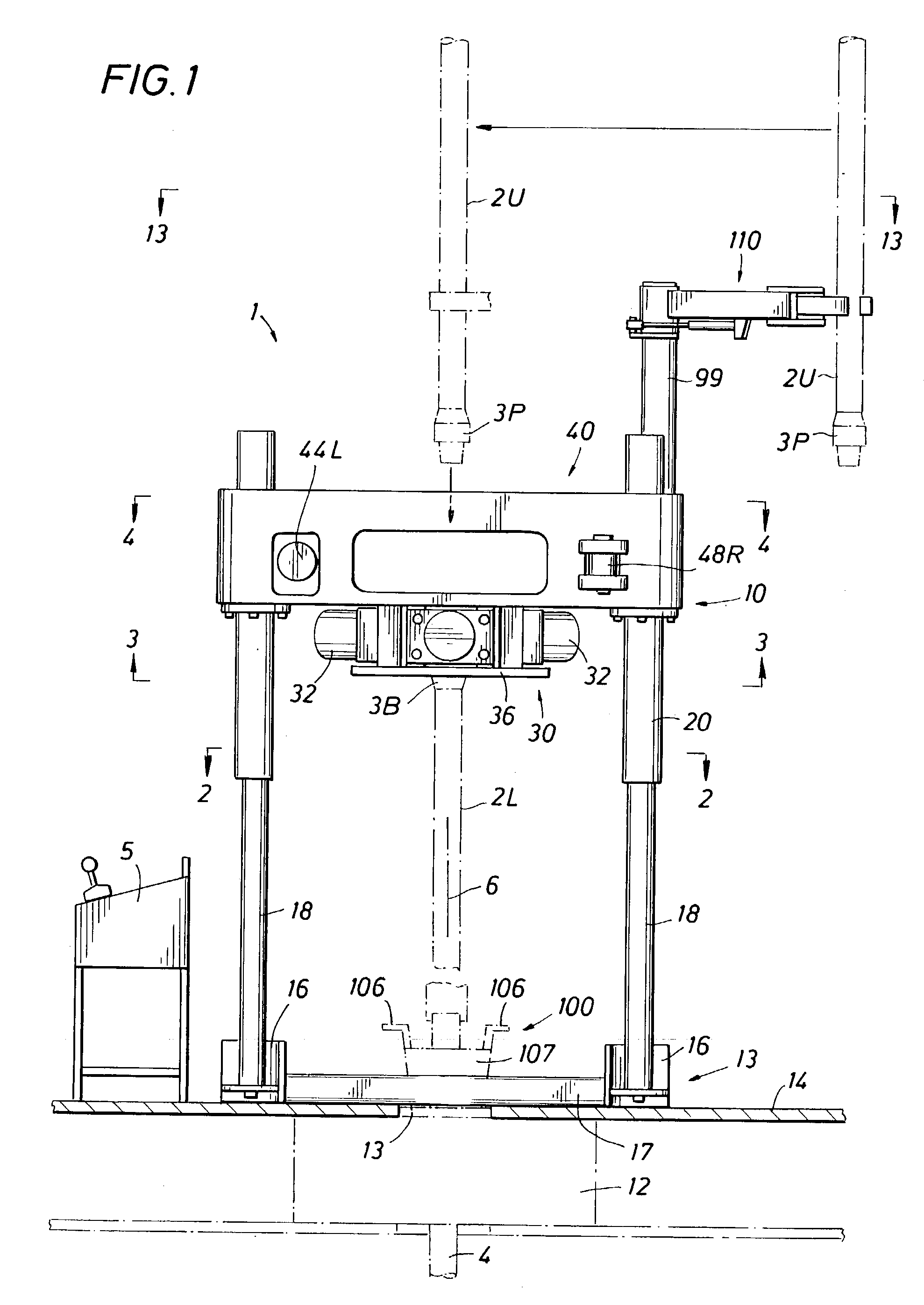
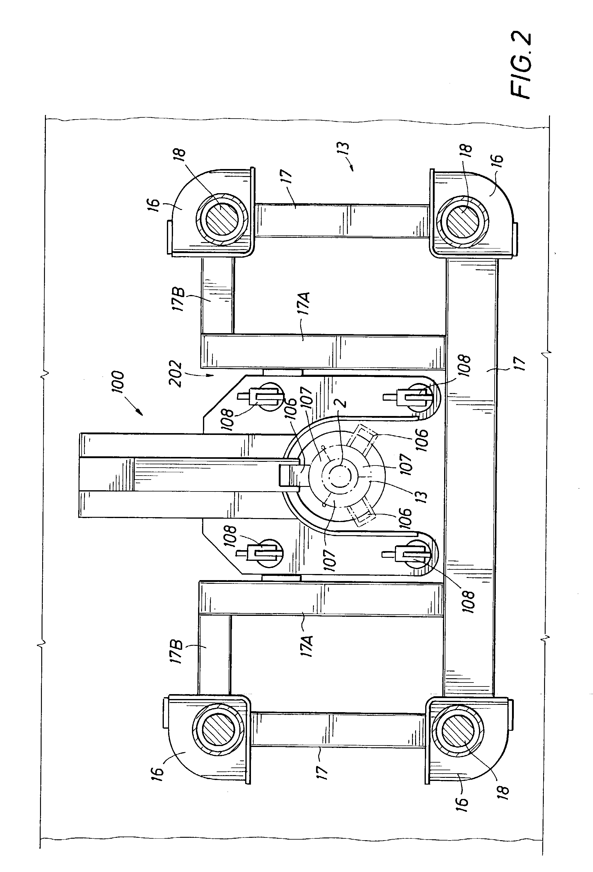
[0039] The description which follows refers to the appended drawings and by reference numbers to specific parts and assemblies. The list which follows correlates reference numbers with part names.

1 1 Remotely controlled assembly for connecting and disconnecting drill pipe 2L Lower drill pipe section 2U Upper drill pipe section 3B Box coupling or upset 3P Pin coupling or upset 4 Drill string 5 Control panel 6 Well centerline 10 Drill pipe connecting and disconnecting tool (Powered Wrenches) 12 Rotary table 13 Opening to rotary table 14 Rig floor 16 Base foot 17 Base structural member 17A, B Base structural members for slot for powered slip assembly 18 Vertical rods 20 Hydraulic cylinder on vertical rods 30 Lower wrench 32 Piston for lower wrench 34 Jaw for lower wrench 36 Bottom plate for lower wrench 40 Wrench assembly mounted on hydraulic cylinder 42 Frame 42U Top frame member 42B Bottom frame member 42S Side frame member 44L Left torquing cylinder for upper wrench 44 Flanges on cy...


PUM


Abstract

Drilling rig apparatus for connecting and disconnecting well pipe at a drilling rig. A remotely controlled power wrench assembly is mounted on a remotely controlled lifting mechanism attached to a base spaced about the well axis on the rig floor. The wrench assembly includes upper and lower wrenches carried by the lifting mechanism. The wrench assembly includes a lower wrench for gripping a lower box coupling of a drill pipe section at the well center. An upper wrench is provided for spinning an upper pin coupling into or out of threaded engagement with the lower box coupling. The upper wrench has two opposed spinner-roller pairs which translate between open and closed positions for spinning the upper pin coupling when in a closed position. The upper wrench also has two opposed jaw blocks which translate between open and closed positions for gripping the pin coupling in a closed position. The spinner roller pairs and the jaw blocks move in directions perpendicular to each other into and out of a cavity through which the well axis passes vertically. Torque cylinders are provided by which the upper wrench is torqued in a first or "torquing up" direction while the jaw blocks are gripping the pin coupling and in a second or "breaking loose" direction. A manipulator is pivotably carried on a rod supported from the wrench assembly. The manipulator includes a remotely controlled arm and hand assembly which captures a drill pipe section in its hand and transfers the drill pipe while being supported vertically by the drilling rig between the well axis and a position at the side-of the wrench assembly. The drilling rig apparatus includes a bore arranged and designed for placement on the rig floor around the well axis. A slot is provided between frame members for placement of a pneumatically remotely controlled power slip manipulator for setting and releasing slips in the rotary table for supporting the drill pipe string in the well bore during connecting and disconnecting operations of drill pipe sections.

Description

[0001] This non-provisional patent application is based upon provisional patent application No. 60 / 384,195 filed on May 30, 2002, the priority date of which is claimed.[0002] 1) Field of the Invention[0003] This invention relates generally to rotary drilling apparatus for oil and gas wells and in particular to apparatus for remotely controlling spinning and torquing operations for drill pipe joints or sections of drill pipe joints while going into a hole (connecting joints) or coming out of a hole (disconnecting joints) with rotary table / slip equipment of a drilling rig.[0004] In particular, this invention relates to an assembly of three devices for the drilling rig platform: a remotely controlled powered slip for supporting a drill string in the well, a remotely controlled powered wrench assembly for spinning and torquing operations for coupling or decoupling a drill pipe point to a drill pipe joint which is supported by slips at the rotary table, and a remotely controlled powered ...

Claims


Application Information

Patent Timeline
Patent Type & Authority Applications(United States)
IPC IPC(8): E21B19/14E21B19/16
CPCE21B19/14E21B19/168E21B19/164E21B19/163
Inventor HAMILTON, WILLIAM R.FLETCHER, DAVID CURTISRAE, DONALD D.
Owner FORUM US
Why Eureka
Try Eureka