Automatic voltage selection in a DC power distribution apparatus

Inactive Publication Date: 2003-12-04
AM GROUP
View PDF3 Cites 59 Cited by
  • Summary
  • Abstract
  • Description
  • Claims
  • Application Information

AI Technical Summary

Problems solved by technology

The transformers, in turn, not only further complicate the tangle of cords, but they also are expensive and not entirely reliable.
Most individuals with systems of this type often find themselves complaining about the plethora of wires providing further

Method used


Image

  • Automatic voltage selection in a DC power distribution apparatus
  • Automatic voltage selection in a DC power distribution apparatus
  • Automatic voltage selection in a DC power distribution apparatus

Examples


Embodiment Construction

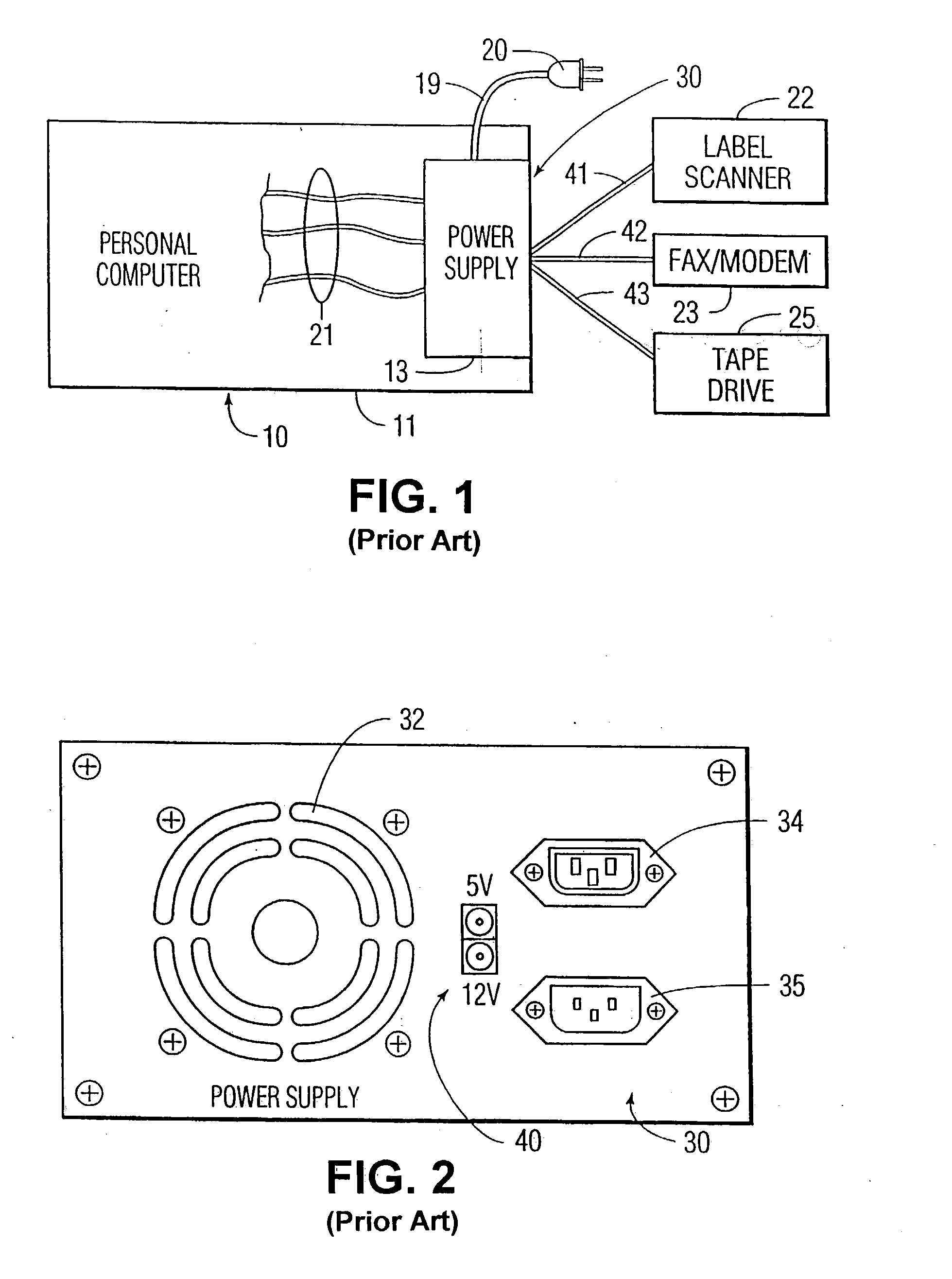
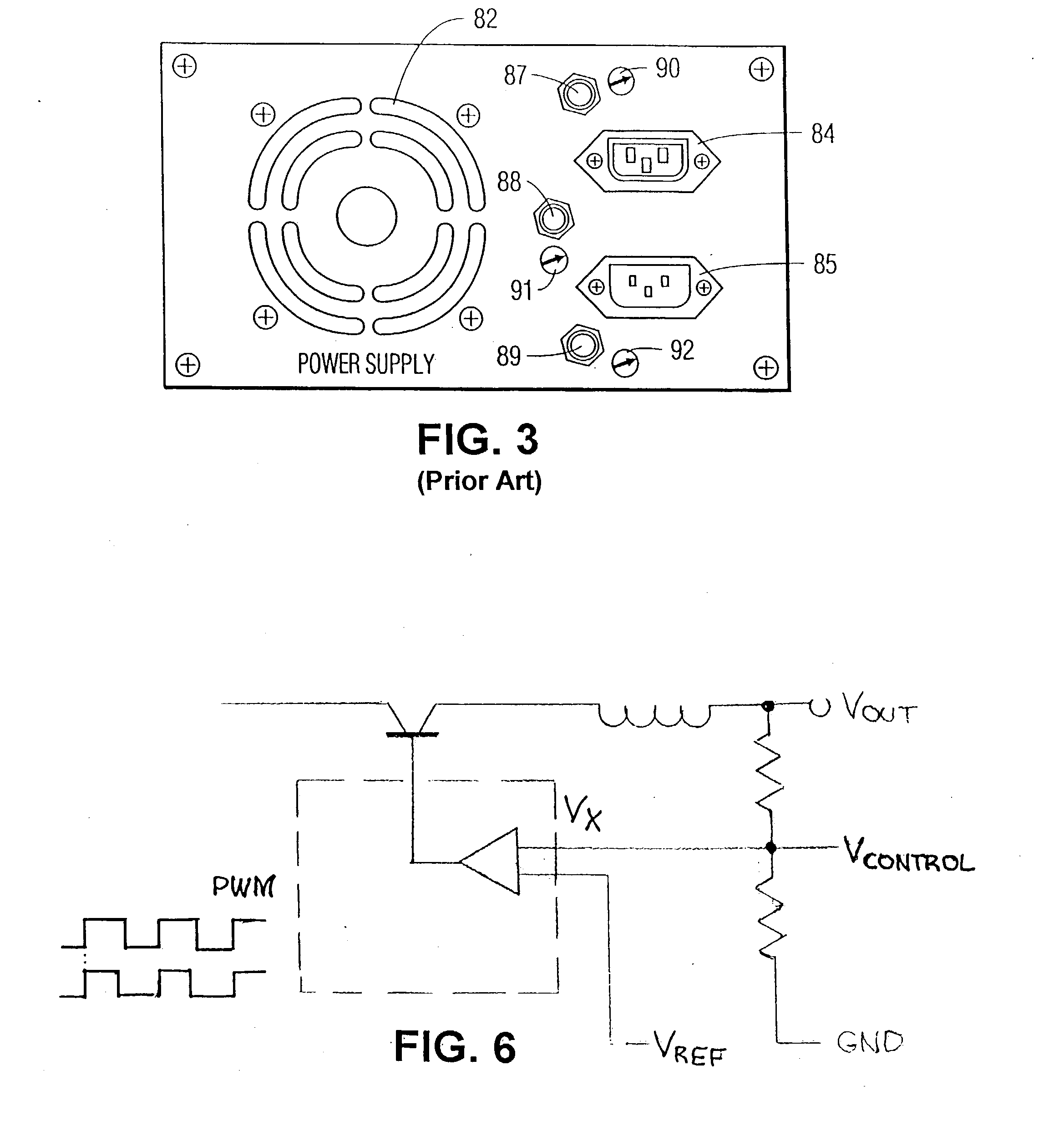
[0023] Reference will be made first to prior art FIGS. 1-3 to provide a basis for understanding the unique improvement of the invention.

[0024] FIG. 1 shows a personal computer 10 having a housing 11. A power supply 13 (with a voltage regulator (not shown)) is located within the housing. The power supply is connected to an in-the-wall socket (or equivalent) as indicated by cord 19 and plug 20. Power supply 13 is connected electrically to components (not shown) within the housing which constitute typical components for a computer for supplying power to those components as shown by wires 21. Typical peripherals for a computer are, for example, a LABEL scanner 22, a FAX / MODEM 23, and a tape drive (or CD ROM) 25 shown also connected to internal power supply 13.

[0025] FIG. 2 shows a face of a typical power supply for a personal computer. The power supply typically is secured within housing 11 with face 30 visible at an aperture in the computer housing.

[0026] The power supply includes a fa...


PUM


Abstract

Provision is made in the housing of a host to provide a socket, or sockets, to which a peripheral piece of equipment can be connected for receiving directly from the host the low voltage DC power it requires. The socket(s) are connected electrically to the outputs of a power supply (or regulator) of a host for providing the low voltage needed to power the peripheral. The power supply may be mounted on the rear face of a computer. The principal feature of the invention resides in the use of a connector for connecting the host DC power to the peripheral DC power usage device. The connector comprises pins connected to a selected resistor in the power supply. The resistor value (i.e., resistance) is selected to produce a pre-determined control voltage which is fed back to a DC to DC converter in the host's internal power supply. The converter comprises a pulse width modulation control device. The control voltage determines the duty cycle (i.e., pulse width) of the modulation to reduce the output from a maximum voltage to an appropriate voltage suitable for the particular peripheral power usage device. Thus, by simply selecting the appropriate connector (or cable) having the proper pins correlated to a selected resistor previously installed in the power supply, the voltage level for the corresponding peripheral device is automatically selected. In an alternative embodiment, the DC power distribution apparatus of the present invention comprises a stand-alone unit having one or more universal ports for receiving a cable with a connector containing the appropriate pins for a selected DC power usage device.

Description

CROSS-RELATED APPLICATIONS[0001] This application is a continuation-in-part of application Ser. No. 09 / 891,926 filed Jun. 26, 2001.[0002] 1. Field of the Invention[0003] This invention relates to DC power distribution from a source to a peripheral device wherein the appropriate voltage level is selected automatically.[0004] 2. Prior Art[0005] The market is replete with electronic equipment to which peripheral equipment is connected for cooperative action. The personal computer is one example of equipment to which peripheral equipment such as a FAX / modem and a LABEL scanner are connected for communication purposes. Another example is the television set to which a video cassette recorder (VCR) is connected; another, a stereo system. A tape drive, which might be connected to any of the above hosts, is a particularly familiar peripheral. Each piece of peripheral equipment is connected separately to an in-the-wall socket for power, as well as to the host, leading to a tangle of cords cha...

Claims


Application Information

Patent Timeline
IPC IPC(8): G06F1/26H01R13/66H01R29/00H02J1/10
CPCG06F1/266H01R13/6616H02J1/10H01R29/00H01R13/6675
Inventor LAM, PHILLIP L.ARAKI, JOHN K.
Owner AM GROUP
Why Eureka
Try Eureka