Rewinding machine with auxiliary cylinders and respective winding method

a technology of auxiliary cylinders and winding cylinders, which is applied in the direction of web handling, thin material handling, transportation and packaging, etc., can solve the problems of inability to exceed the critical rotation speed of the assembly formed by the mandrel and the reel being formed, the eccentricity of the winding core, and the difficulty in controlling the reel at such speeds, so as to reduce vibration, increase production speed, and accurate control of the developing reel

Inactive Publication Date: 2003-12-25
A CELLI NONWOVENS
View PDF3 Cites 12 Cited by
  • Summary
  • Abstract
  • Description
  • Claims
  • Application Information

AI Technical Summary

Benefits of technology

[0009] Object of the invention is to make a peripheral rewinding machine, specifically of the start-stop type, which provides a more accurate control of the developing reel by reducing vibrations and consequently allowing production speed increases. Another object of the invention is a winding method providing a more accurate control of the winding conditions.
[0010] Essentially, according to the invention, a rewinding machine is provided, comprising: a first and a second lower winding roller defining a winding cradle for a reel of web; a third upper roller whose axis is mobile arranged over said first and second lower winding roller and carried by two mobile slides to allow for the increasing dimension of the reel under formation in said winding cradle. Characteristically, the two slides carry two cylinders whose axes are parallel to the axis of said third upper roller, which are provided with a reciprocal approaching and distancing movement for either approaching or distancing the reel being formed in said cradle. The two cylinders which are arranged by the side of the third winding roller form a more "wrapping" winding cradle with the three winding rollers for the reel or roll being formed. This arrangement consequently controls the vibrations in a more effective and reliable way.
[0011] In essence, the reel being formed can be held in contact with five points defined by an equal number of cylinders or rollers during at least one part of the winding cycle. The lower rollers are motor driven while the third upper roller and the two cylinders parallel to the latter can be either driven or idle. The first solution is preferred because the reel can be turned more efficiently.
[0012] The two cylinders are advantageously and preferably arranged symmetrically with respect to a vertical plane containing the axis of the third upper roller, despite other arrangements being possible in line of principle. The approaching and distancing movement of the cylinders with respect to the reel under formation can be a translation movement. For example, the cylinders may for this purpose be fifted on mobile saddles or slides. Preferably, however, the cylinders are pivotally supported on an axis which is parallel to the axis of the third winding roller. Each of the two cylinders can be supported on a respective pivoting axis. However, the two cylinders can preferably be mounted on the same axis, which preferably coincides with the rotation axis of the third roller over the cradle defined by the first two winding rollers. This arrangement simplifies transmission of motion to the two cylinders.
[0017] This method ensures a better control of the reel during formation thereof, particularly during the intermediate portion of the winding cycle.

Problems solved by technology

Controlling the reel may be very difficult at such speeds.
Such difficulties are particularly due to the fact that the winding mandrels on which the cores where the web reels will be formed are heavy in weight and tend to deflect by effect of their own weight.
Other reported problems refer to eccentricity of the winding cores and winding mandrel inserted inside.
Furthermore, the critical rotation speed of the assembly formed by the mandrel and the reel being formed are relative low and cannot be exceeded due to evident problems of dynamics.
Controlling the reel may become very difficult due to these vibrations because of insufficient guiding and hold of the reel being formed, which can also reach very large diameters, in the order of 1-2 meters.

Method used


Image

  • Rewinding machine with auxiliary cylinders and respective winding method
  • Rewinding machine with auxiliary cylinders and respective winding method
  • Rewinding machine with auxiliary cylinders and respective winding method

Examples


Embodiment Construction

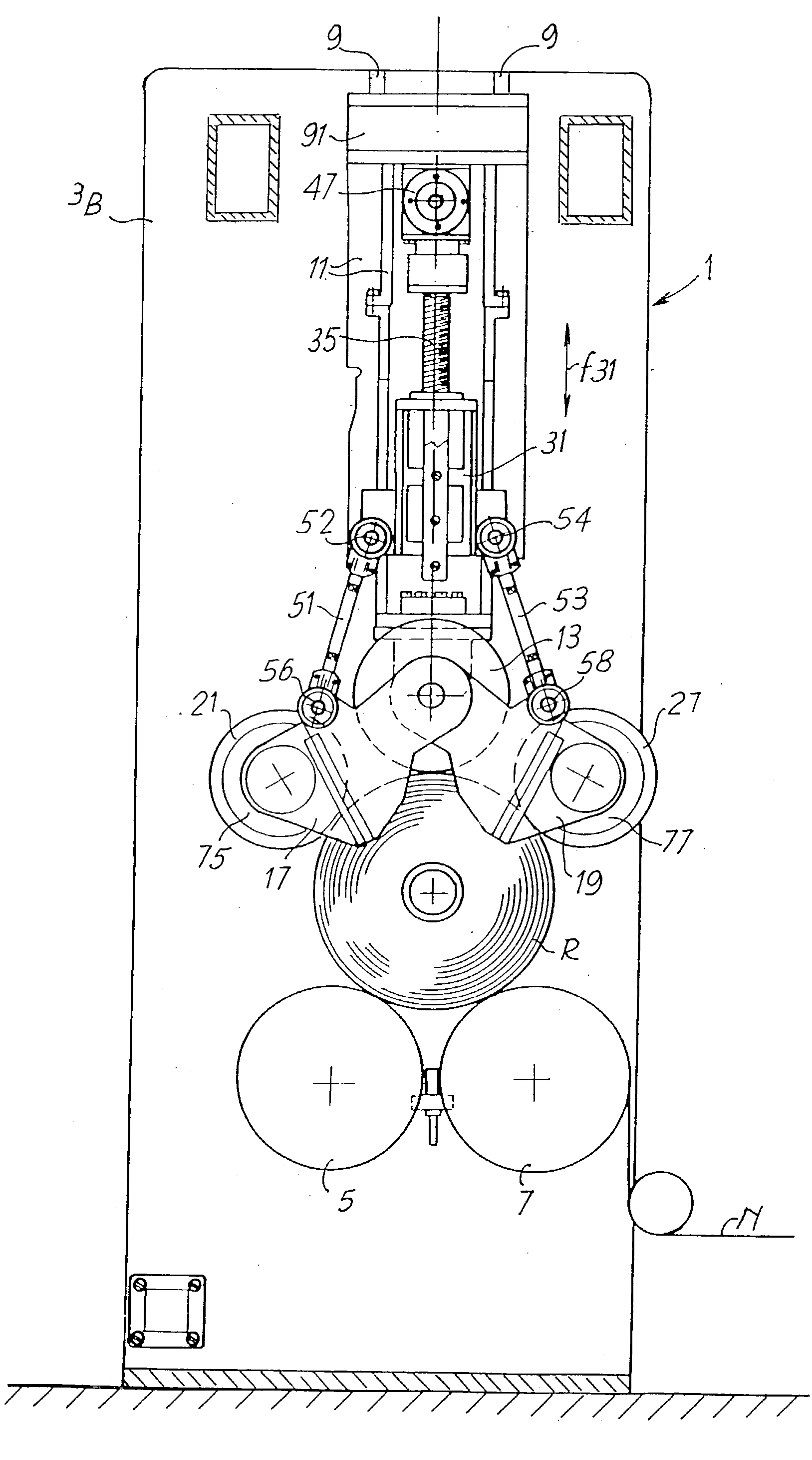
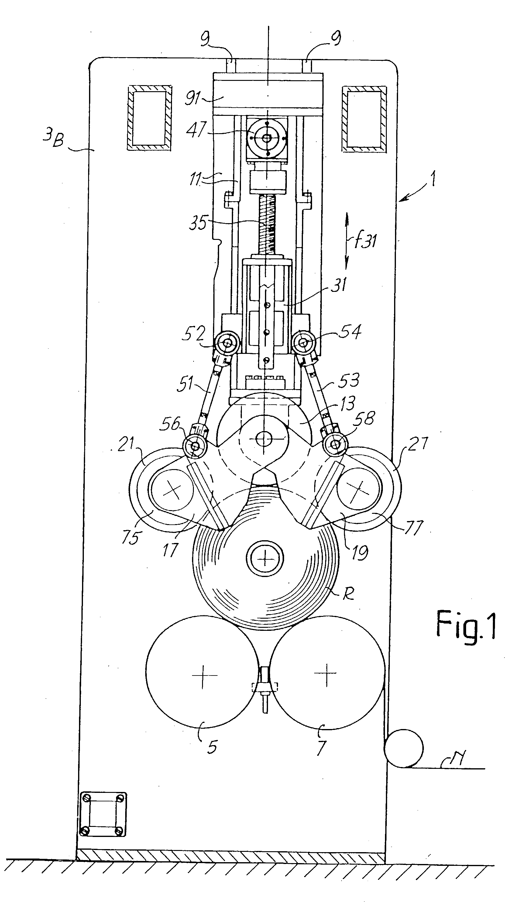
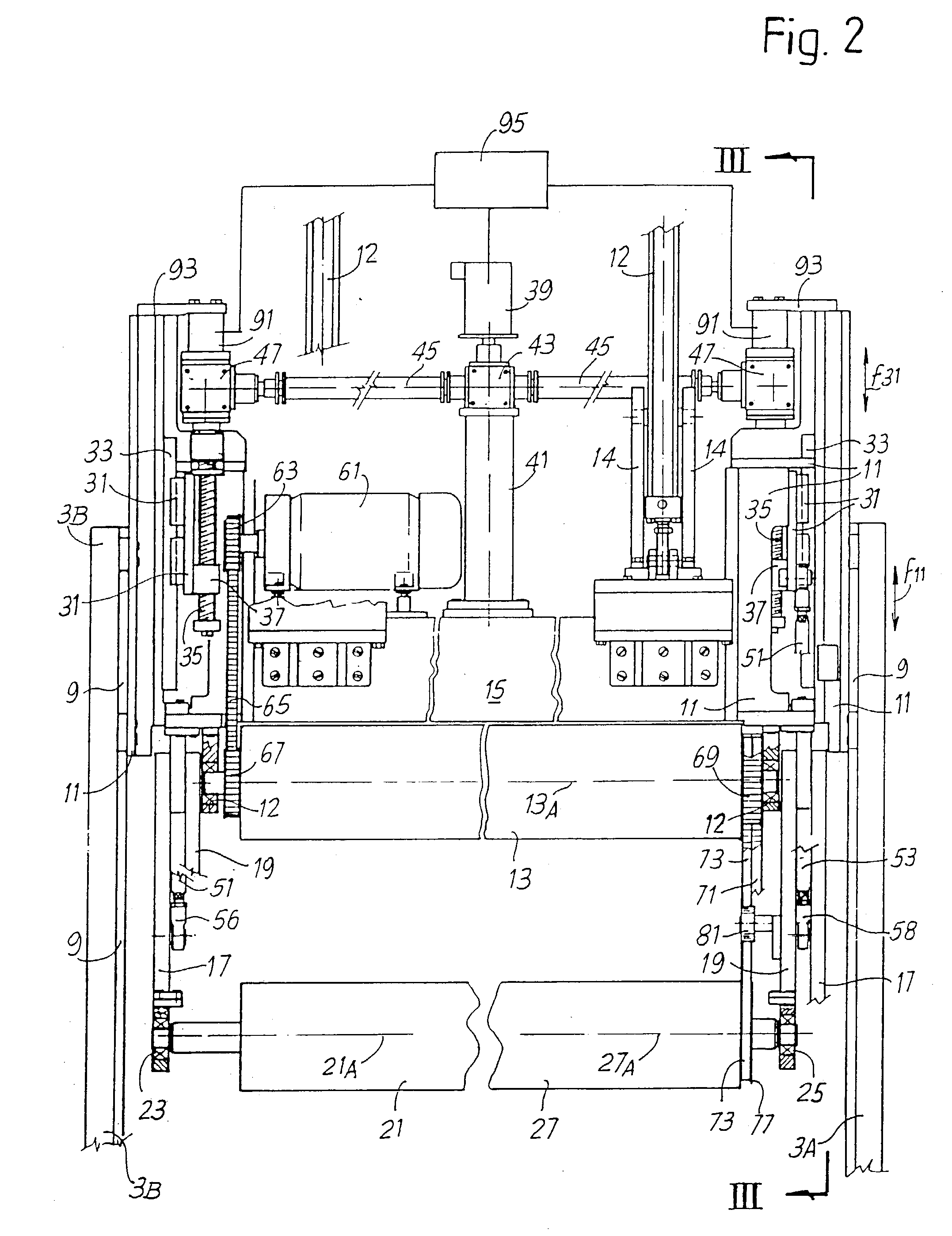
The accompanying figures show the salient parts of the rewinding machine except for the components, assemblies and elements which are known per se and are not relevant for understanding the invention. Specifically, the devices for inserting the winding mandrel, unloading the finished reel and for cutting the web at the end of the winding cycle are not shown. The mandrel controlling mating centers, which may be used and which are however known to experts in the field, are also not illustrated.

[0025] Reference is made in this description to the development of a reel on the winding mandrel. In actual fact, the reel can be formed by a plurality of single reels arranged side-by-side which simultaneously receive the same length of web, since the winding cycle can be carried out on tubular cores axially aligned on the mandrel by winding strips of web obtained by longitudinally cutting a single incoming web. Consequently, the term "reel" can herein indicate a single reel or a plurality of a...


PUM


Abstract

The rewinding machine comprises: a first and a second lower winding roller (5, 7) defining a winding cradle for a reel (R) of web (N); a third upper roller (13) having a mobile axis (13) arranged over said first and second lower winding rollers and carried by two mobile slides (11) to allow for the increasing dimension of the reel under formation in said winding cradle. The two slides (11) carry two cylinders (21, 27) whose axes are parallel to the axis (13A) of the third upper roller (13) which are provided with a reciprocal approaching and distancing movement for either approaching or distancing the reel under formation in said cradle.

Description

[0001] The invention relates to a peripheral rewinding machine, specifically of the so-called start-stop type, i.e. in which the supply of web to be wound is interrupted or delayed to replace the completed reel with a new winding mandrel. More particularly, the invention relates to a rewinding machine comprising: a first and a second lower winding roller defining a winding cradle for a web material reel under formation; a third upper roller whose axis is mobile arranged over the winding cradle formed by the first and the second lower winding rollers and carried by two mobile slides to allow for the increasing dimension of the reels being formed in the winding cradle.[0002] The invention also relates to a peripheral winding method for reels of web.STATE OF THE ART[0003] Operations concerning winding or rewinding web are required in the sector of non-woven processing, e.g. in the production of reels of semifinished materials intended for the production of sanitary towels, diapers and ...

Claims


Application Information

Patent Timeline
Patent Type & Authority Applications(United States)
IPC IPC(8): B65H18/20
CPCB65H18/20B65H2404/432B65H2404/43
Inventor ACCIARI, GIUSEPPE
Owner A CELLI NONWOVENS
Why Eureka
Try Eureka