Stabilization structures for CPP sensor

a technology of stabilization structure and cpp sensor, which is applied in the field of magnetic transducers, can solve the problems of difficult magnetic stabilization and achieve the effect of improving the stability of the free (sense) layer

Inactive Publication Date: 2003-12-25
HITACHI GLOBAL STORAGE TECH NETHERLANDS BV
View PDF4 Cites 63 Cited by
  • Summary
  • Abstract
  • Description
  • Claims
  • Application Information

AI Technical Summary

Problems solved by technology

When the CPP sensor is used, magnetic stabilization of the free (sense) layer can be difficult ...

Method used


Image

  • Stabilization structures for CPP sensor
  • Stabilization structures for CPP sensor
  • Stabilization structures for CPP sensor

Examples


first embodiment

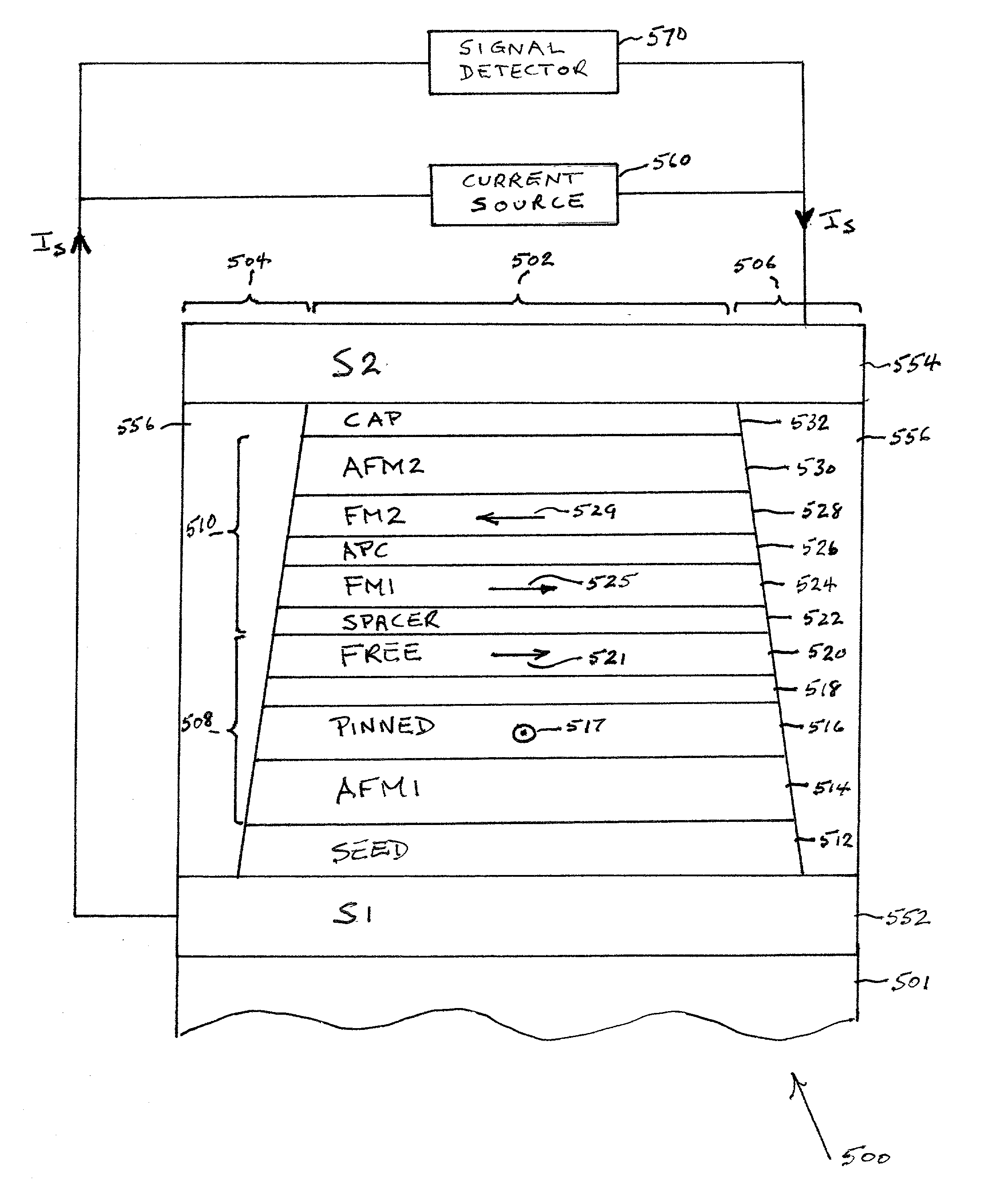
[0037] FIG. 5 shows an air bearing surface (ABS) view, not to scale, of a CPP spin valve (SV) sensor 500 according to the present invention. The SV sensor 500 comprises end regions 504 and 506 separated from each other by a central region 502. The active region of the SV sensor comprises a CPP spin valve (SV) stack 508 and a longitudinal bias stack 510 formed in the central region 502. The seed layer 512 is a layer deposited to modify the crystallographic texture or grain size of the subsequent layers, and may not be needed depending on the subsequent layer. The SV stack 508 sequentially deposited over the seed layer 512 comprises a first antiferromagnetic (AFM1) layer 514, a ferromagnetic pinned layer 516, a conductive spacer layer 518 and a ferromagnetic free (sense) layer 520. The AFM1 layer 514 has a thickness, typically 50-500 .ANG., at which the desired exchange properties are achieved with the pinned layer 516.

[0038] The longitudinal bias stack 510 sequentially deposited over...

second example

[0049] FIG. 6 shows an air bearing surface (ABS) view, not to scale, of a CPP magnetic tunnel junction (MTJ) sensor 600 according to a second embodiment of the present invention. The MTJ sensor 600 differs from the SV sensor 500 in having an MTJ stack 608 in place of the SV stack 508. The active region of the MTJ sensor comprises the MTJ stack 608 and the longitudinal bias stack 510 formed in the central region 502. The MTJ stack 608 sequentially deposited over the seed layer 512 comprises a first antiferromagnetic (AFM1) layer 514, a ferromagnetic pinned layer 516, an insulating tunnel barrier layer 618 and a ferromagnetic free (sense) layer 520. The insulating tunnel barrier layer 618, preferably formed of Al.sub.2O.sub.3, replaces the conductive spacer layer 518 of the CPP SV sensor 500 of the first example.

[0050] The longitudinal bias stack 510 sequentially deposited over the MTJ stack 608 has the same structure as the bias stack of the first example including a spacer layer 522...


PUM


Abstract

Current-perpendicular-to-plane (CPP) spin valve (SV) and magnetic tunnel junction (MTJ) sensors are provided having an antiparallel (AP)-coupled longitudinal bias stack for instack biasing to stabilize the free layer. A CPP sensor comprises a longitudinal bias stack adjacent to and in contact with a free (sense) layer of the sensor. The bias stack comprises an antiparallel (AP)-pinned layer including FM1 and FM2 layers separated by an antiparallel coupling (APC) layer. The FM1 layer is separated from the free layer of the sensor by a nonmagnetic spacer layer. By choosing the relative thicknesses of the FM1 and FM2 layers, the bias field HB from the AP-pinned layer and the ferromagnetic coupling field HFC between the FM1 layer and the free layer is made additive at the free layer for either positive or negative coupling. By ensuring that the bias field adds to the coupling field, the stability of the free layer by in-stack longitudinal biasing is improved.

Description

[0001] 1. Field of the Invention[0002] This invention relates in general to magnetic transducers for reading information signals from a magnetic medium and, in particular, to a current perpendicular to the plane sensor with an improved stabilization structure which allows addition of ferromagnetic coupling and magnetostatic bias at the free layer.[0003] 2. Description of the Related Art[0004] Computers often include auxiliary memory storage devices having media on which data can be written and from which data can be read for later use. A direct access storage device (disk drive) incorporating rotating magnetic disks is commonly used for storing data in magnetic form on the disk surfaces. Data is recorded on concentric, radially spaced tracks on the disk surfaces. Magnetic heads including read sensors are then used to read data from the tracks on the disk surfaces.[0005] In high capacity disk drives, magnetoresistive (MR) read sensors, commonly referred to as MR sensors, are the prev...

Claims


Application Information

Patent Timeline
IPC IPC(8): G01R33/09G11B5/00G11B5/012G11B5/39H01F10/32
CPCG11B5/3903G11B5/3909G11B5/3932G11B5/3967G11B2005/0008G11B2005/3996H01F10/3286H01F10/3268B82Y10/00B82Y25/00G01R33/093G11B5/012H01F10/3254
Inventor GILL, HARDAYAL SINGH
Owner HITACHI GLOBAL STORAGE TECH NETHERLANDS BV
Why Eureka
Try Eureka