High-frequency, low-temperature regenerative heat exchanger

a regenerative heat exchanger, low-temperature technology, applied in the direction of domestic cooling equipment, lighting and heating equipment, machines/engines, etc., can solve the problems of low efficiency of cryogen storage tanks and accompanying insulation and thermal-structural isolators, inability to meet long-life space-based applications, and inability to meet the requirements of long-life space-based applications

Inactive Publication Date: 2004-01-01
RAYTHEON CO
View PDF13 Cites 45 Cited by
  • Summary
  • Abstract
  • Description
  • Claims
  • Application Information

AI Technical Summary

Problems solved by technology

Unfortunately, the cryogen storage tanks and accompanying insulation and thermal-structural isolators are often prohibitively bulky, especially for space-based applications involving lengthy operation and high heat loads.
Currently, stored cryogen technologies that provide cooling to liquid helium temperatures (4.2 Kelvin (K)) are impractical for long-life space-based applications.
Unfortunately, existing flexure-bearing closed-cycle cryocoolers exhibit significant performance degradation below 35 K, which is undesirably high for some applications.
The operation of flexure-bearing cryocoolers below 35 K is limited by the lack of efficient regenerator designs for enabling requisite low-temperature and high-frequency operation.
These cryocoolers, which are based on regenerative thermodynamic cycles, are often undesirably bulky and incapable of producing very cold cryogenic temperatures below 35 K. The lack of efficient regenerators with sufficient heat capacity to enable high frequency operation at low temperatures has limited reductions in cryocooler sizes and operating temperatures.
These systems may operate at cryogenic temperatures below 35 K, but they are undesirably bulky for many applications.
Lead remains practical at temperatures down to approximately 15 K, which remains undesirably high for some applications.
Unfortunately, the specific heats of stainless steel and brass are prohibitive for regenerative heat exchange below 40 K.
However, rare earth metals and intermetallic compounds are often brittle and nonmalleable.
Spheres have an undesirably low surface area-to-volume ratio and provide excessively high porosity for efficient operation at low temperatures.
Conventionally, the success of closed-cycle, reciprocating, flexure-bearing cryocoolers has been limited to systems operating at 35 K and above due to the lack of a regenerator capable of efficiently operating at very low temperatures and high frequencies.
Very small cryogenic cooling systems may not provide extremely cold cryogenic temperatures below 35 K. Cooling systems that can produce very low temperatures are often undesirably bulky and are limited to low frequency operation.
Shortcomings in conventional regenerator designs, including problems with materials selection and geometric structure, prevent current cooling technologies from achieving compact size, high-frequency operation, and extremely cold cryogenic temperatures simultaneously.
Furthermore, the use of parallel sheets of plated substrate results in low-pressure drop and high heat transfer efficiency between the working gas and the accompanying regenerator.
Due to shortcomings in conventional regenerator designs, the efficiency of the ideal Stirling cycle in conventional regenerative cycle cryocoolers is not adequately approximated at liquid helium temperatures and high frequency.

Method used


Image

  • High-frequency, low-temperature regenerative heat exchanger
  • High-frequency, low-temperature regenerative heat exchanger
  • High-frequency, low-temperature regenerative heat exchanger

Examples


Embodiment Construction

[0032] While the present invention is described herein with reference to illustrative embodiments for particular applications, it should be understood that the invention is not limited thereto. Those having ordinary skill in the art and access to the teachings provided herein will recognize additional modifications, applications, and embodiments within the scope thereof and additional fields in which the present invention would be of significant utility.

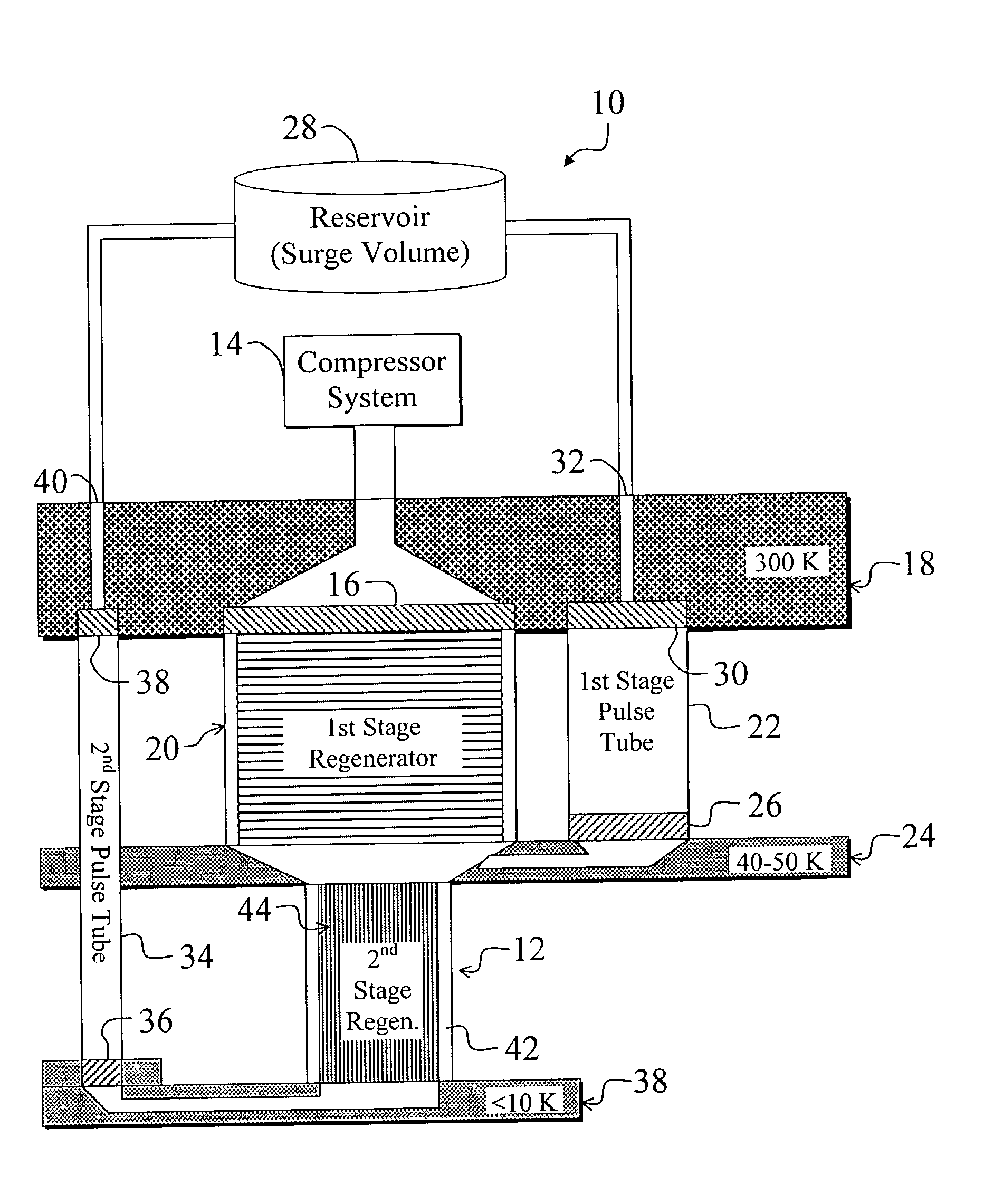
[0033] FIG. 1 is a block diagram of an exemplary two-stage pulse tube cryocooler 10 employing an efficient second stage regenerator 12 constructed in accordance with the teachings of the present invention. For clarity, various well-known components, such as power supplies, motors, compressor valves, acoustic phase shift networks, and so on, have been omitted from the figures, however those skilled in the art with access to the present teachings will know which components to implement and how to implement them to meet the needs of a g...


PUM

PropertyMeasurementUnit
temperaturesaaaaaaaaaa
operating frequencyaaaaaaaaaa
thicknessaaaaaaaaaa

Abstract

A high-frequency, low-temperature regenerator (12). The regenerator (12) includes a substrate (50) having rare earth material (52) disposed thereon. In a specific embodiment, the substrate (50) has channels or pores (54) therethrough or therein to facilitate gas flow through the regenerator (12). The substrate (50) is constructed from a material, such as polyimide, polyester, or stainless steel, which is sufficient to define the geometry of the regenerator (12). The rare earth material (52) is selected and deposited on the substrate (50) in a layer (52) having thermal penetration depth that is greater than the thickness of the layer (52). The thermal penetration depth is sufficiently high to enable all of the rare earth material (52) to contribute to thermal regeneration at an operating frequency of 30 Hz. In the illustrative embodiment, the thickness of the substrate (50) is less than or equal to approximately 0.001 inches. The layer of rare earth material (52) is approximately 0.0002 inches thick. The substrate (44, 50) includes a stack of plated substrates (44) that are stacked so that spaces (54) exist between the plated substrates (44), which result in a porosity of approximately 15 percent. Dimples, pleats, or other mechanisms in the plated substrates (44) preserve the spaces (54) between the plated substrates (44). In the specific embodiment, the spaces (54) are approximately 0.00025 inches wide, and the working gas is helium.

Description

[0001] 1. Field of Invention[0002] This invention relates to regenerative thermodynamic systems and methods. Specifically, the present invention relates to regenerators used in systems employing regenerative thermodynamic cycles, such as pulse tube and Stirling cycle cryogenic coolers and engines.[0003] 2. Description of the Related Art[0004] Cryogenic cooling systems are employed in various demanding applications including space, cellular telephony, and high-speed computing. Such applications often demand efficient, compact, lightweight cryocoolers capable of establishing and maintaining the lowest possible cryogenic temperatures.[0005] Efficient cryocoolers are particularly important in space-based applications, where size, weight, and cooling requirements are especially stringent. Space-based systems, such as satellites, space shuttles, and exo-atmospheric missiles, often employ sophisticated electronics and sensors that require cryogenic cooling for optimal operation.[0006] Stor...

Claims


Application Information

Patent Timeline
Patent Type & Authority Applications(United States)
IPC IPC(8): F25B9/14F28D17/02
CPCF02G2243/52F25B9/10F25B9/145F25B2309/003F28D17/02F25B2309/1413F25B2309/1415F25D19/006F25B2309/1408
Inventor KIRKCONNELL, CARL S.OZGUZ, VOLKAN
Owner RAYTHEON CO
Why Eureka
Try Eureka