Apparatus and method for controlling intake air amount of internal combustion engine
- Summary
- Abstract
- Description
- Claims
- Application Information
AI Technical Summary
Problems solved by technology
Method used
Image
Examples
Embodiment Construction
[0029] An embodiment of the present invention will be described based on the drawings.
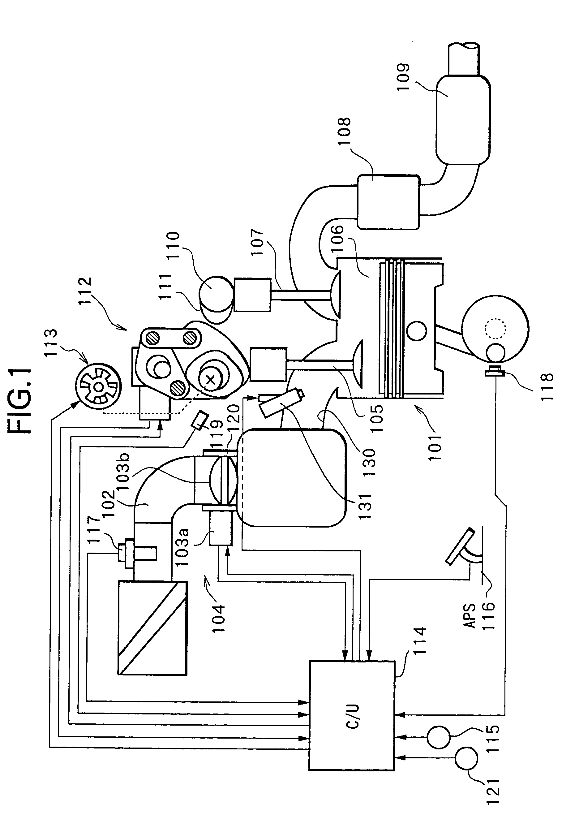
[0030] FIG. 1 is a structural diagram of an internal combustion engine for vehicle. In FIG. 1, in an intake passage 102 of an internal combustion engine 101, an electronically controlled throttle 104 is disposed for driving a throttle valve 103b to open and close by a throttle motor 103a. Air is sucked into a combustion chamber 106 via electronically controlled throttle 104 and an intake valve 105.
[0031] A combusted exhaust gas is discharged from combustion chamber 106 via an exhaust valve 107, purified by an exhaust purification catalyst 108, and then emitted into the atmosphere via a muffler 109.
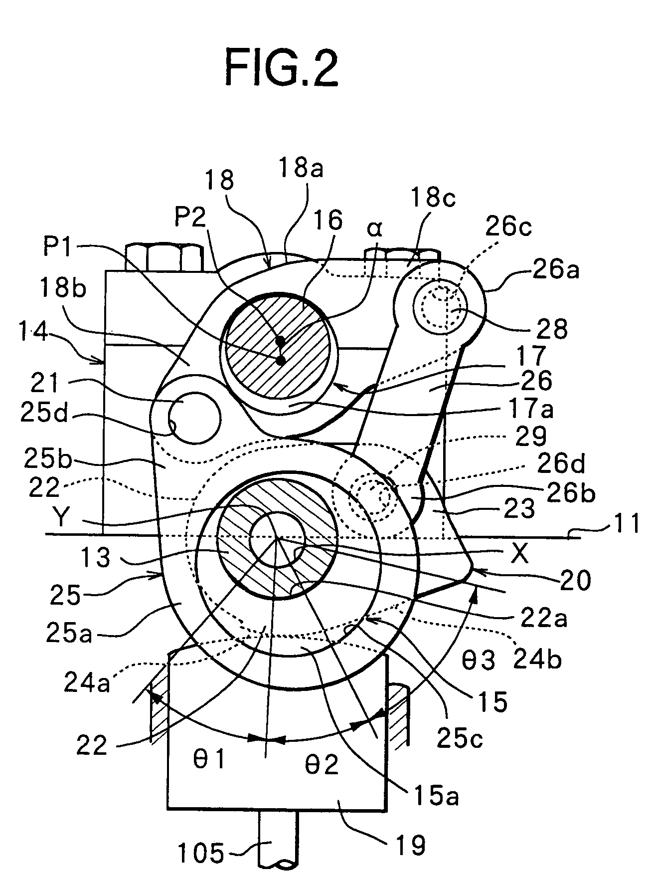
[0032] Exhaust valve 107 is driven by a cam 111 axially supported by an exhaust side camshaft 110, while keeping a valve lift amount and a valve operating angle thereof constant. On the contrary, a valve lift amount and a valve operating angle of intake valve 105 are successively varied by a VEL (Variable...
PUM
 Abstract
Description
Claims
Application Information
 - R&D
- Intellectual Property
- Life Sciences
- Materials
- Tech Scout
- Unparalleled Data Quality
- Higher Quality Content
- 60% Fewer Hallucinations
Browse by: Latest US Patents, China's latest patents, Technical Efficacy Thesaurus, Application Domain, Technology Topic, Popular Technical Reports.
© 2025 PatSnap. All rights reserved.Legal|Privacy policy|Modern Slavery Act Transparency Statement|Sitemap|About US| Contact US: help@patsnap.com


