Television audience interaction system

a technology for interaction systems and televisions, applied in the field of television, can solve problems such as the general limitation of prior-art audience response systems

Inactive Publication Date: 2004-01-15
VOGEL PETER S
View PDF12 Cites 21 Cited by
  • Summary
  • Abstract
  • Description
  • Claims
  • Application Information

AI Technical Summary

Benefits of technology

0005] It is an object of the present invention to provide an audience response s

Problems solved by technology

These prior-art audience response systems are generally limited in

Method used


Image

  • Television audience interaction system
  • Television audience interaction system
  • Television audience interaction system

Examples


Embodiment Construction

[0015] Some preferred embodiments of the invention will now be described with reference to the drawings in which:

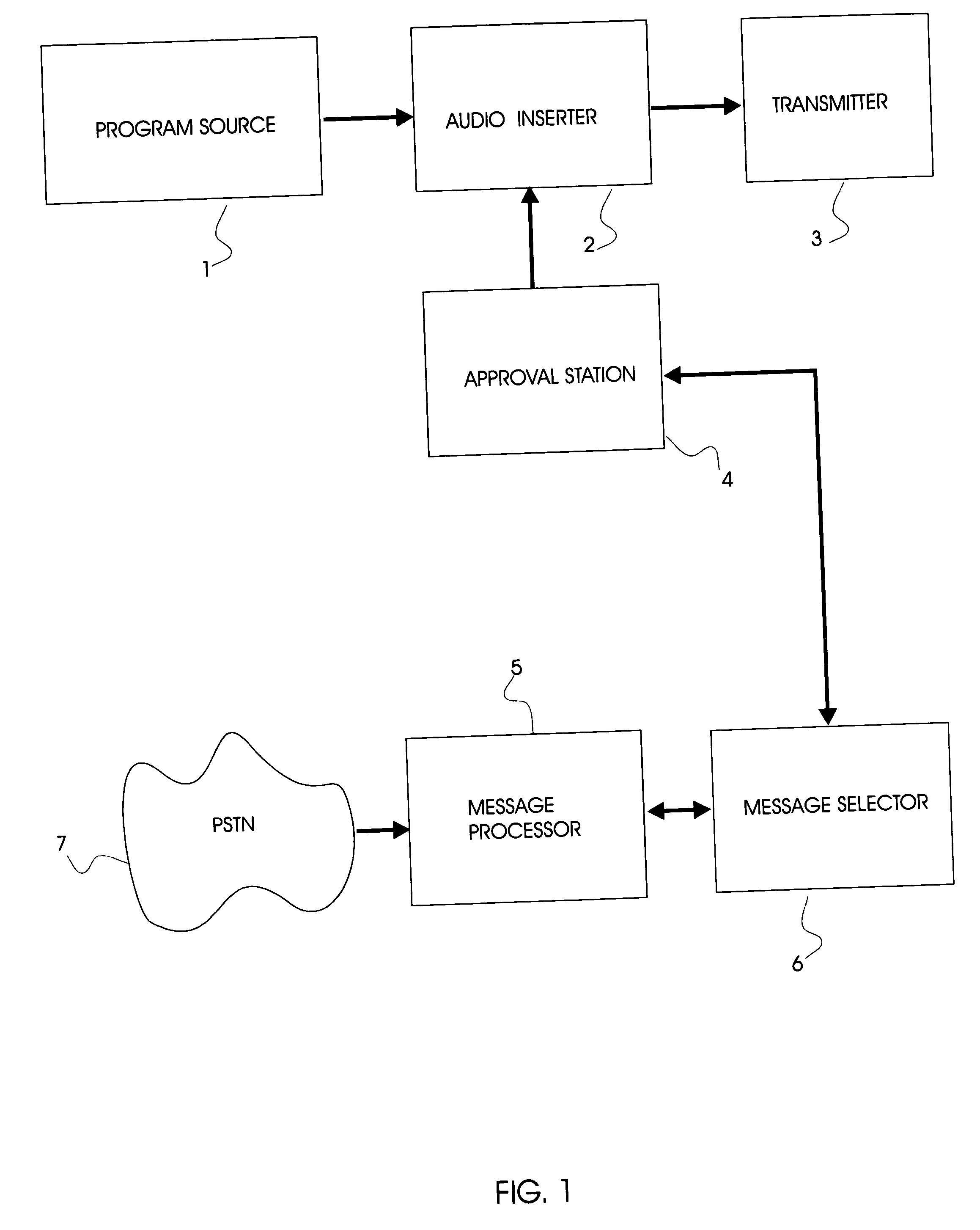
[0016] FIG. 1. is a block diagram of the invention wherein the audience response messages are inserted at the program transmission station; and

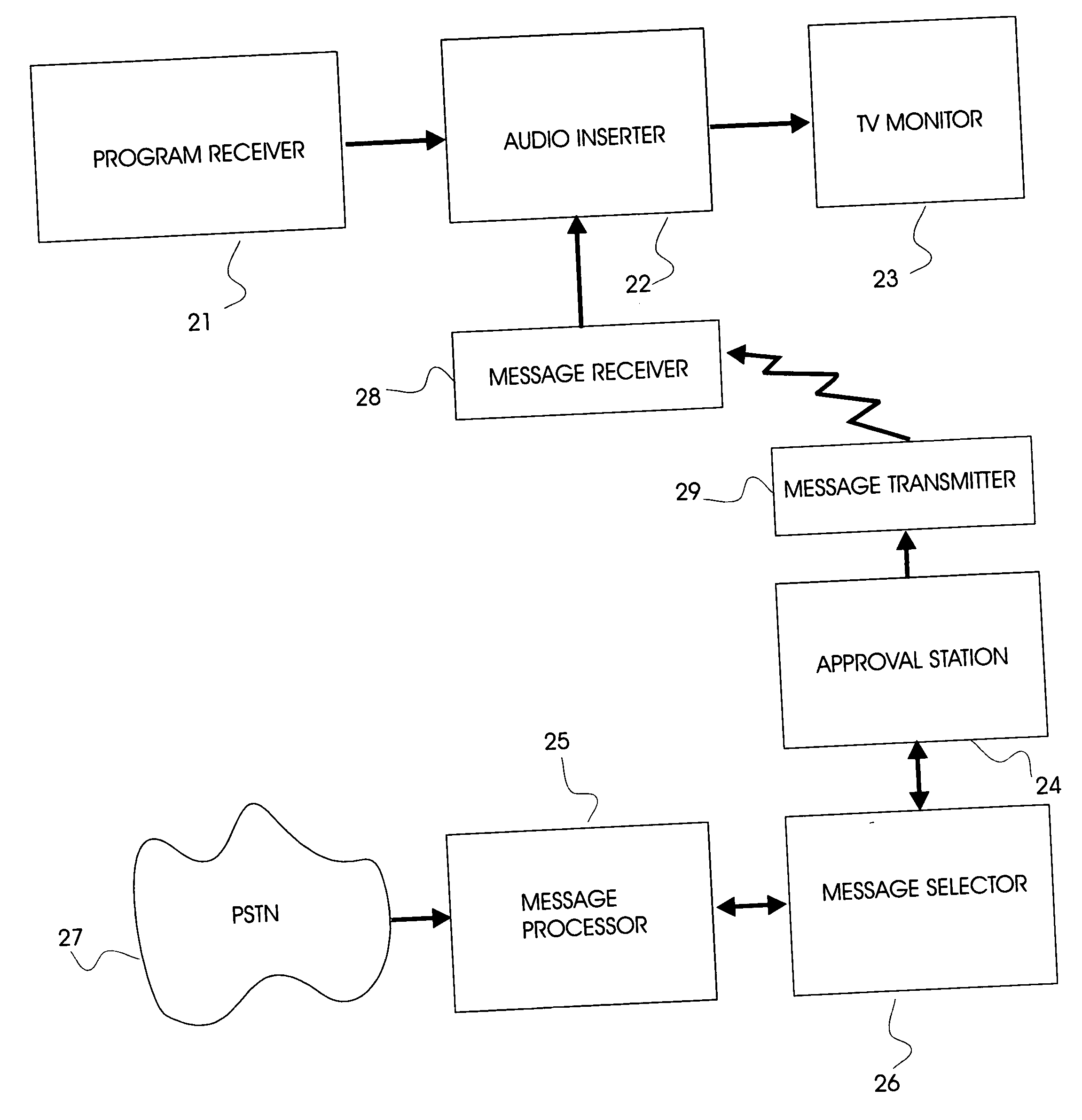
[0017] FIG. 2 is a block diagram of the invention wherein the audience response messages are inserted at the program receiving station.

[0018] Referring now to FIG. 1, the embodiment shown inserts messages submitted by members of the public into the audio portion of the program being transmitted.

[0019] In this embodiment, messages can be submitted to the broadcaster via Public Switched Telephone Network PSTN (7) which feeds message receiver (5). Message receiver (5) translates each message received into a suitable digital format, creating message files which are stored in a suitable memory system. Message submission is charged to the submitter by well-known means, for example by means of premium charges on telephone accounts, or by ...


PUM


Abstract

A systems for inserting feedback from members of the viewing public into a television program. Viewers submit reactions to programming in realtime in the form of spoken messages, text messages, or graphics which are incorporated into the program being watched or into a separate program broadcast subsequently. The invention has many applications in the entertainment industry, including, for example, making television programs more entertaining and creating an extra revenue source for broadcasters.

Description

[0001] This invention relates to systems of inserting voice messages from members of the viewing public into a television program.[0002] The present invention has many applications in the entertainment industry, including, for example, making television programs more entertaining and creating an extra revenue source for broadcasters.PRIOR ART[0003] It is well known in the television industry to invite the public to respond to or interact with programs, for example by writing letters, sending emails, or making phone calls. For example, the program "Big Brother" relies upon the public to phone in and vote for which people are to be evicted from the show. Other programs use polling via telephone, mail or Internet to provide public opinion statistics. In most cases the broadcaster's objective in providing such facilities is to raise revenue, typically by charging premium rates for telephone calls through mechanisms such as "1900" facilities.[0004] These prior-art audience response syste...

Claims


Application Information

Patent Timeline
IPC IPC(8): H04H1/00H04H20/38H04H60/07H04H60/33H04H60/82H04H60/91H04H60/94H04N7/173H04N21/258H04N21/44H04N21/442H04N21/475H04N21/4786H04N21/4788H04N21/81
CPCH04H20/38H04N21/8106H04H60/33H04H60/82H04H60/91H04H60/94H04N7/17309H04N21/258H04N21/25891H04N21/44016H04N21/44222H04N21/4756H04N21/4786H04N21/4788H04H60/07
Inventor VOGEL, PETER S.
Owner VOGEL PETER S
Why Eureka
Try Eureka