
Trolley wheel mechanism

Inactive Publication Date: 2004-01-22
ARROW TECH SYST
View PDF13 Cites 1 Cited by
  • Summary
  • Abstract
  • Description
  • Claims
  • Application Information

AI Technical Summary

Benefits of technology

[0005] The invention is directed towards providing for simpler and easier user control of a trolley. A related object is to reduce risk of injury, such as back pain, for users, by reducing the push and pull forces required for a trolley. An example is movement of a trolley into and out of a galley in an airplane or train

Problems solved by technology

This is awkward for users.
It appears that a good deal of skill would be required to effectively use the handle and that it is likely to be accidently knocked into an undesired position.

Method used


Image

  • Trolley wheel mechanism
  • Trolley wheel mechanism
  • Trolley wheel mechanism

Examples


Embodiment Construction

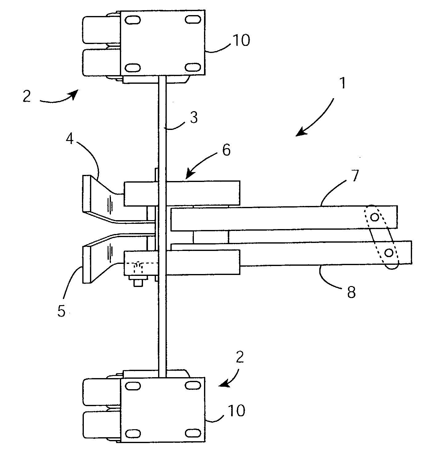
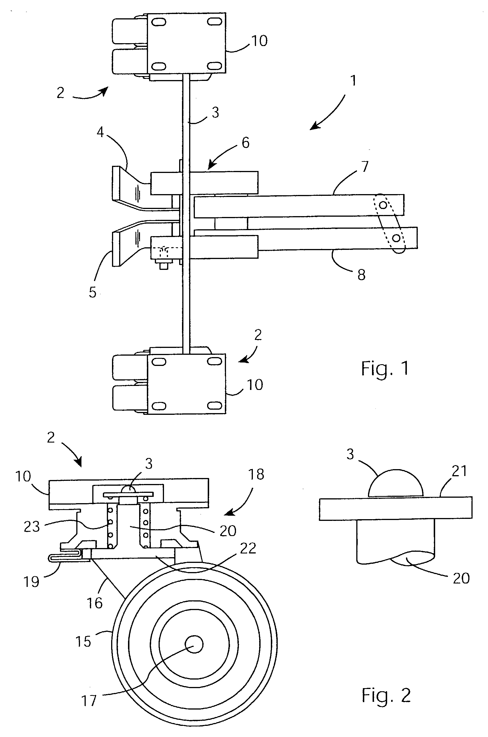
[0034] Referring to FIG. 1, a wheel mechanism 1 comprises a pair of wheel assemblies 2 interconnected by a cam shaft 3. The mechanism 1 also comprises a release pedal 4 and an apply pedal 5 connected to the cam shaft 3 to rotate it to three operative positions, described below. The connection to the cam shaft 3 is via a pedal mechanism 6. The pedal mechanism 6 is connected to link arms 7 and 8 to transfer pedal movements to another mechanism for the trolley, and vice versa. Also, the link arms 7 and 8 are interconnected as shown so that they transfer movement to each other. Each wheel assembly 2 comprises a base plate 10 for securing by bolts to the trolley (not shown).

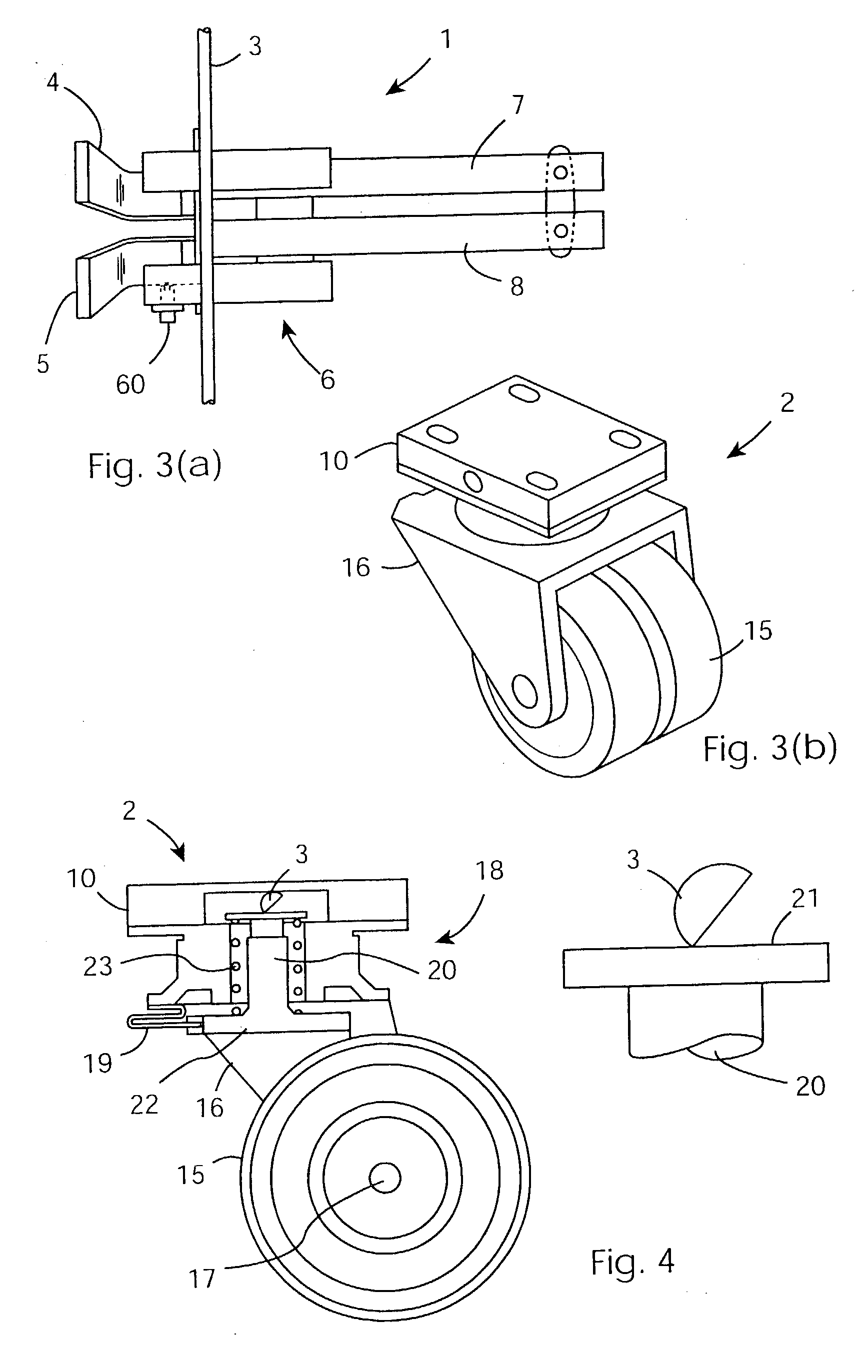
[0035] Referring to FIG. 2 and FIG. 3(b), each wheel assembly 2 comprises a pair of side-by-side wheels 15, and an inverted U-shaped bracket 16 supporting an axle 17 for the wheels 15. The bracket 16 is part of a rotatable housing 18 supporting a resilient retainer lock 19 (which rotates with the housing).

[0036] The b...


PUM


Abstract

A trolley wheel mechanism (1) has two caster wheel assemblies (2) each having a pair of wheels (15) mounted on a rotatable housing (18). In a free mode the wheels (15) are free to both rotate and to swivel. This is caused by the user pressing a release pedal (4). In a unidirectional mode a retainer lock (19) engages a brake disc (22) to prevent swivelling of the housing (18). This is caused by the user pressing both pedals (4, 5) simultaneously. A brake mode is caused by the user pressing the apply pedal (5).

Description

[0001] The invention relates to trolleys, and more particularly to caster wheel mechanisms for trolleys.PRIOR ART DISCUSSION[0002] Caster wheels have been used for trolleys for many years. By virtue of their swivelling action they allow trolleys to be easily manoeuvred in confined spaces.[0003] It is also known to provide a brake mechanism to prevent rotation of the wheels, and a lock mechanism to prevent swivelling of the wheels. British Patent Specification No. 1010363 describes such an arrangement. However, the action to prevent swivelling appears to lock the wheels at whichever swivel position they happen to be at. This is awkward for users. Also, little detail is disclosed about how the user operates the mechanisms.[0004] British Patent Specification No. 1438530 describes a wheel mechanism in which a single handle is rotated through various angular positions for different modes of operation. It appears that a good deal of skill would be required to effectively use the handle an...

Claims


Application Information

Patent Timeline
IPC IPC(8): B60B33/02B62B5/04B64D11/00
CPCB60B33/0018B60B33/0042B60B33/0049B60B33/0057Y10T16/195B60B33/0073B60B33/0081B60B33/021B60B33/025B60B33/0068
Inventor WALSH, THOMAS DONALTIERNEY, PATRICK
Owner ARROW TECH SYST
Learn More