
Protection of the chromatographic bed in dynamic axial compression chromatography devices

a technology of dynamic axial compression and chromatography, which is applied in the direction of instruments, other chemical processes, separation processes, etc., can solve the problems of bed deformation, increased pressure exerted by the piston, and the apparatus cannot achieve precise chromatographic bed compaction,

Inactive Publication Date: 2004-01-29
NOVASEP SA
View PDF7 Cites 26 Cited by
  • Summary
  • Abstract
  • Description
  • Claims
  • Application Information

AI Technical Summary

Problems solved by technology

However, this apparatus has the drawback of achieving imprecise compaction of the bed, since this is determined simply by the position of the piston along the tube.
Moreover, there is a risk of the pressure exerted by the piston being greater than the mechanical stresses that the bed can withstand and contact between the bed and the piston may cause the bed to degrade.
Furthermore, this apparatus does not make it possible to take into account the risk of the piston crushing the bed, which may degrade the latter.
It does not make it possible to know the position of the piston along the tube, which may crush the bed.
This is particularly serious when there is a risk of the chromatographic bed being mechanically degraded.
In addition, since the movements of the chromatographic bed are not monitored and the enclosure is unable to discharge the liquid, this apparatus cannot adapt the pressure exerted on the bed according to the movements of the latter and contact between the bed and the piston may degrade the bed.
Moreover, this system cannot be used in SMB (Simulating Moving Bed) or in VARICOL mode.

Method used


Image

  • Protection of the chromatographic bed in dynamic axial compression chromatography devices
  • Protection of the chromatographic bed in dynamic axial compression chromatography devices
  • Protection of the chromatographic bed in dynamic axial compression chromatography devices

Examples


Embodiment Construction

[0062] The device described below allows the chromatography of a fluid to be carried out.

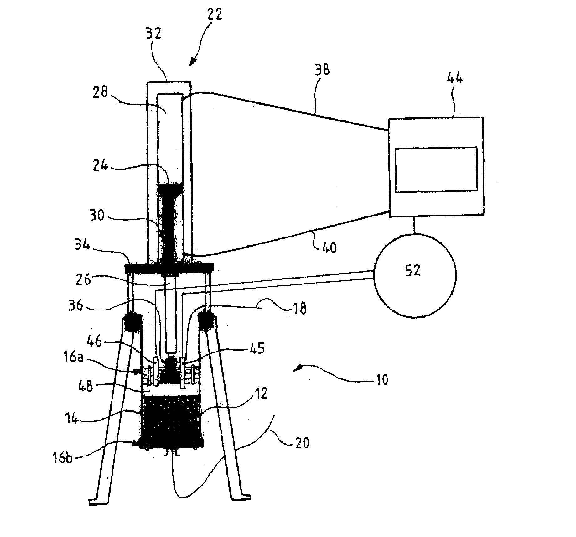
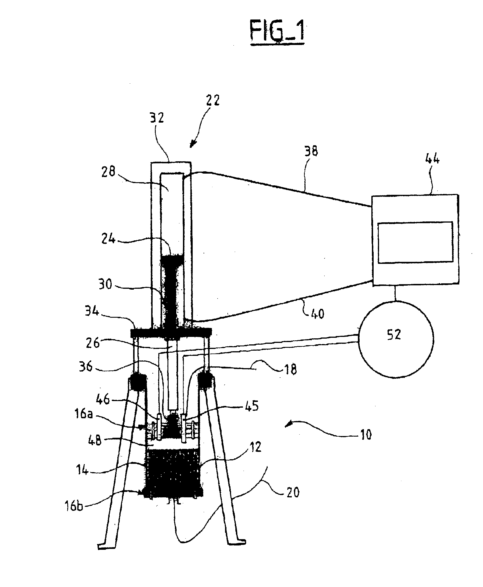
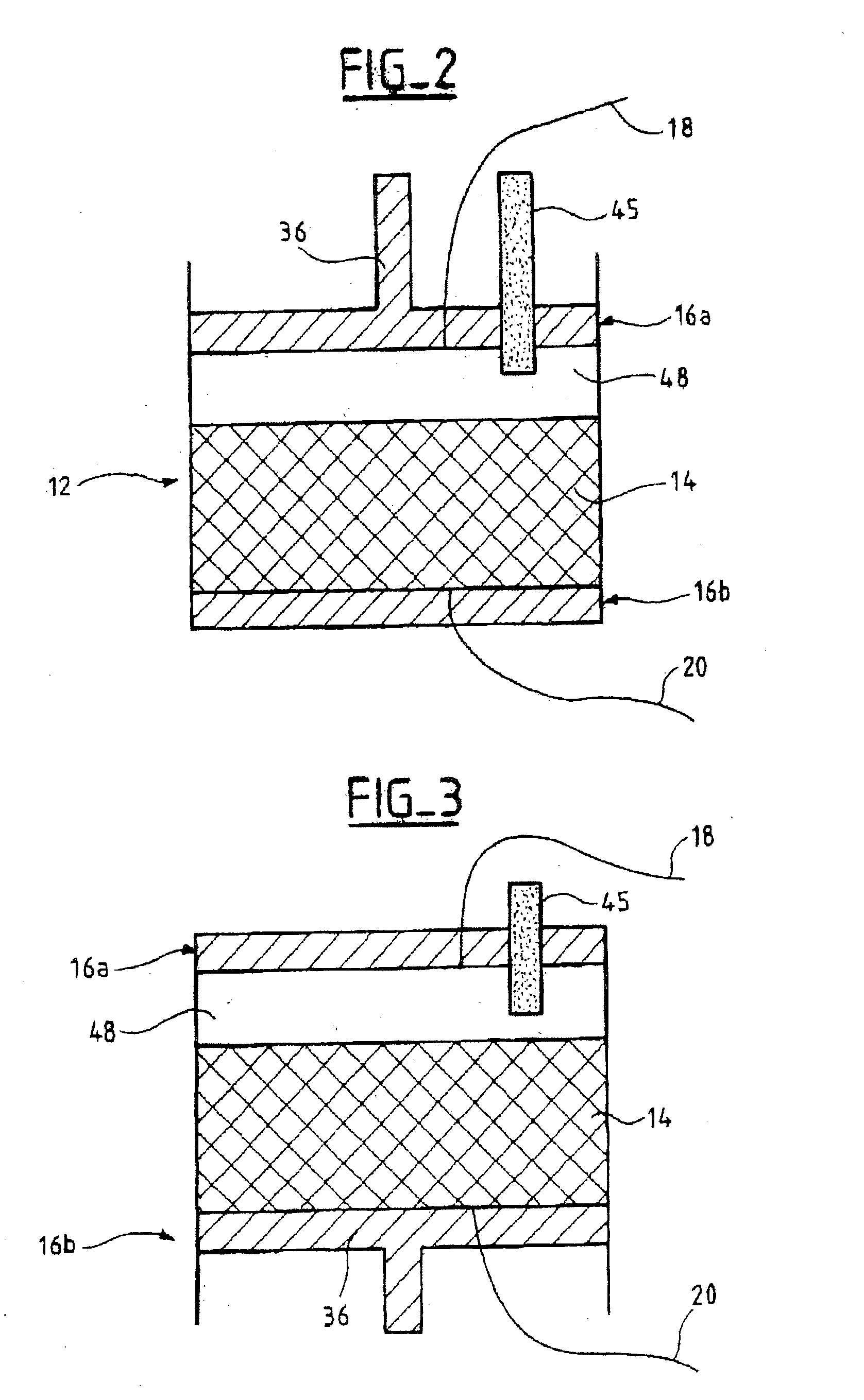
[0063] The chromatography device 10 comprises a column 12 with an upper end 16a and a lower end 16b. The column 12 is intended to house, between its two ends 16a, 16b, a chromatographic bed 14 and the fluid to be chromatographed. The end 16a of the column 12 and a surface of the bed 14 define a fluid layer 48. A piston 36 slides in the column 12. The piston 36 is one of the ends 16a, 16b of the column 12. The device furthermore includes at least a first probe 45 for detecting the surface of the bed 14. The probe 45 is mounted on the end 16a of the column 12 defining the layer 48. The device also includes means 52 for adjusting the position of the piston 36 according to the detection of the surface of the bed 14 by the probe 45.

[0064] FIG. 1 shows schematically the chromatography device 10.

[0065] The chromatographic bed 14 rests on the lower end 16b of the column 12. The bed 14 used is, for examp...


PUM


Abstract

The invention relates to a chromatography device comprising: a column (12) intended to house, between its two ends (16a, 16b) a chromatographic bed (14) and a fluid to be chromatographed, a fluid layer (48) being defined between a surface of the bed (14) and one (16a) of the ends of the column (12); a piston (36) sliding in the column (12), the piston (36) being one of the ends (16a, 16b) of the column (12); at least a first probe (45, 46) for detecting the surface of the bed (14), the probe (45, 46) being mounted on the end (16a) of the column (12) defining the layer (48); and means (52) for adjusting the position of the piston (36) according to the detection of the surface of the bed (14) by the probe (45, 46). The invention also relates to processes for separating at least two compounds of a fluid to be chromatographed and to methods of adjusting the position of the piston with respect to the surface of the chromatographic bed using the chromatography device. The invention has the advantage of allowing effective separation of the compounds of the fluid to be chromatographed while ensuring that the bed is protected.

Description

[0001] The present invention relates to the protection of the chromatographic bed in chromatography devices and in particular in dynamic axial compression devices.TECHNOLOGICAL BACKGROUND[0002] In a chromatography separation process, the effectiveness of the column used is a key parameter. The column is generally filled with a solid product in the form of very fine particles usually having a size within 5 and 100 .mu.m, forming the chromatographic bed. To obtain high effectiveness, the arrangement of the particles inside the column must be as uniform as possible, and empty spaces between the chromatographic bed and the inlet / outlet parts of the column must be avoided. It is known from the prior art to use DAC (Dynamic Axial Compression) columns to ensure that there is a compact bed with no free space between the inlet / outlet distributors and the bed.[0003] Dynamic axial compression columns have a piston or another sliding body driven by a cylinder, actuated, for example, by an indep...

Claims


Application Information

Patent Timeline
IPC IPC(8): G01N27/22B01D15/08B01J20/291G01N30/46G01N30/52G01N30/60G01N30/80G01N30/88
CPCB01D15/08G01N30/52G01N30/6004G01N30/6021G01N2030/522G01N30/62
Inventor HAUCK, WILHELMMARKS, HARLENEBLEHAUT, JEANNICOUD, ROGER MARC
Owner NOVASEP SA
Learn More