Swivel/quick release device for tow rope

a technology of tow rope and quick release, which is applied in the direction of towing/pushing equipment, special-purpose vessels, vessel construction, etc., can solve the problems of skier being caught up, dragged along behind the power boat for a considerable distance, and the tow rope being twisted, so as to prevent knots/kinks, eliminate the twisting of the rope, and prolong the life of the rope

Inactive Publication Date: 2004-02-05
MURPHY MICHAEL +3
View PDF3 Cites 2 Cited by
  • Summary
  • Abstract
  • Description
  • Claims
  • Application Information

AI Technical Summary

Benefits of technology

[0009] The swivel / quick release can be mounted stationary to the tow point of the boat by a bracket with a metal type fastener that may also feature a swivel on the end of the boat attachment to allow the rope to travel left to right freely zero to 360 degrees. It may also be a non-stationary rope swivel attachment of this invention allows the rope attached to it to twist 360 degrees while the skier is using the rope and handle, eliminating twist in the rope and allowing the rope to spin twist free. This swivel mechanism eliminates the problems associated with retrieving and using traditional rope attachments that twist and knot when the rider performs 360 degree / 180 degree tricks and maneuvers. The swivel prevents knots / kinks when in use and extends the life of the rope by reducing wear and tear.
[0010] The release mechanism of this invention serves as a safety devise that releases manually or can be set to release automatically should the skier fall or be caught in the rope or handle. The release feature of this invention allows the rider to set a degree of pressure that will release the rider in the event of an accident.

Problems solved by technology

These activities can cause the tow rope to become twisted.
In the event of a spill, the skier can become entangled in the tow rope or dragged along behind the power boat for a considerable distance.
The skier may also become caught up by the handle carried at the end of the tow rope.

Method used


Image

  • Swivel/quick release device for tow rope
  • Swivel/quick release device for tow rope
  • Swivel/quick release device for tow rope

Examples


Embodiment Construction

[0013] In the drawings:

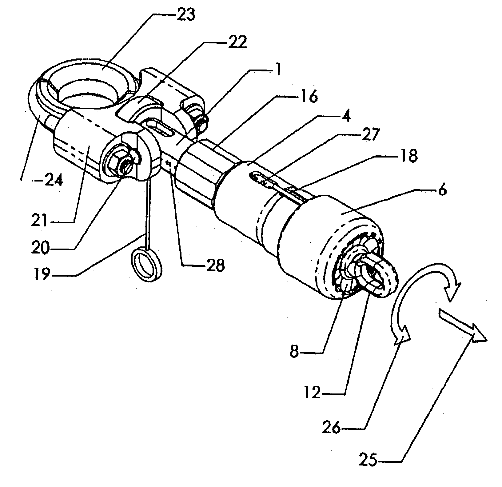
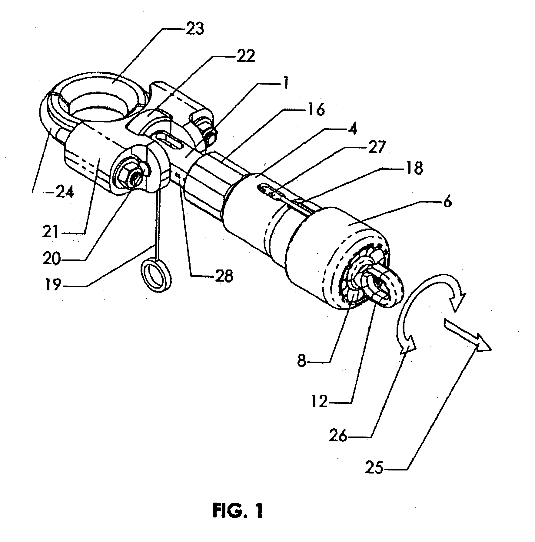
[0014] Figure A is a perspective view of the swivel / quick release of this invention, shown fully assembled.

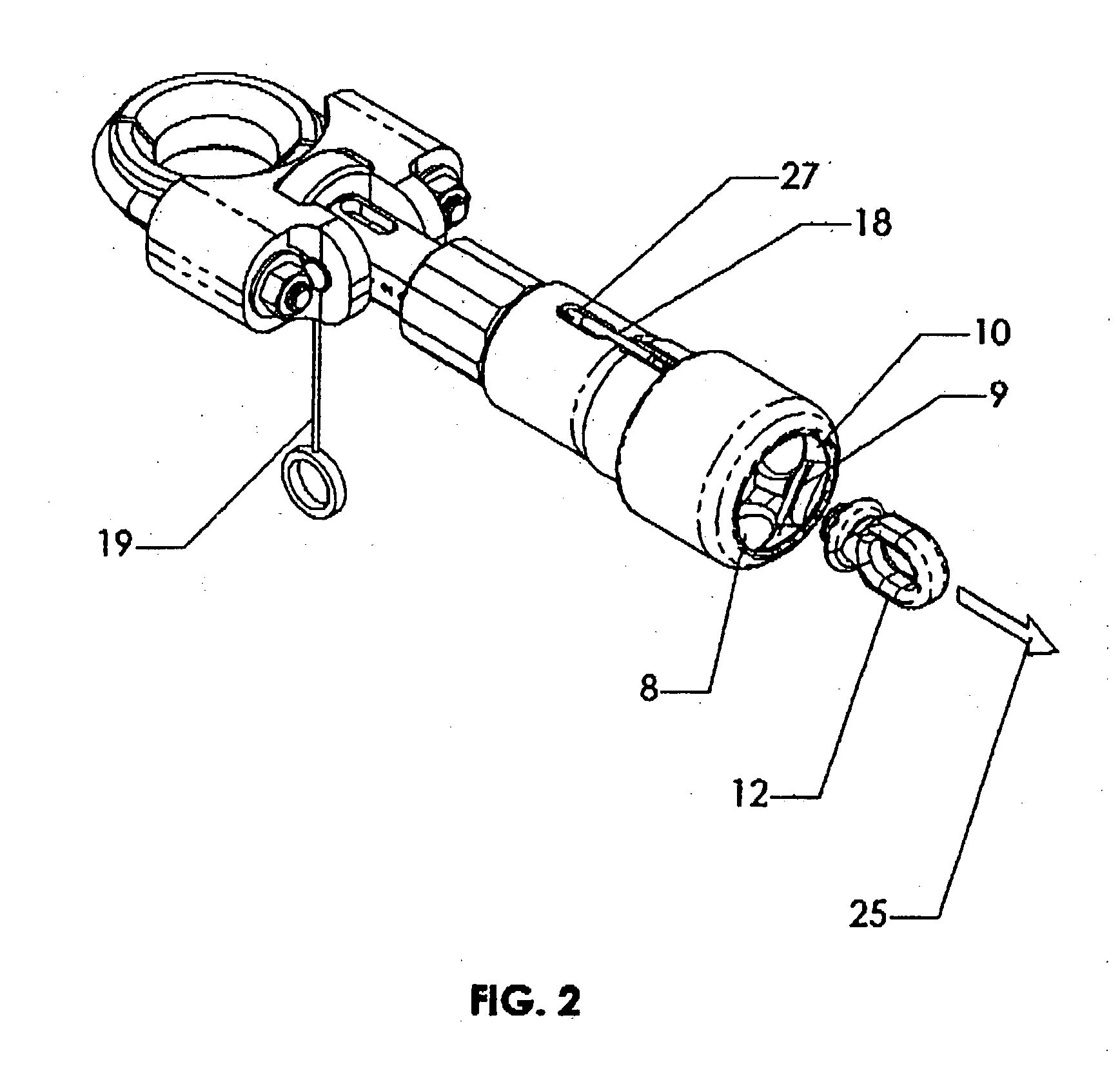
[0015] Figure B is a perspective view of the device of Figure A with rope attachment released by rope overload.

[0016] Figure C is a longitudinal section through the device of Figure A, with no load applied.

[0017] Figure D is a sectional view similar to Figure C, but with the rope under tension but at less than release load.

[0018] Figure E is similar to Figure D with the device shown at release load.

[0019] Figure F is similar to Figure E, but where the release occurs manually rather than by loading.

[0020] Figure G is similar to Figure C with the device adjusted to release at a lighter load.

[0021] Figure H is a partial section perspective view of the device in the state shown in Figure C.

[0022] Figure I is a partial section perspective view of the device in the state shown in Figure D.

[0023] Figure J is a partial section perspective view of the device of Fi...


PUM


Abstract

A swivel / quick release device having a shaft adapted to receive a load at one end operated associated with a bearing means at its other end; a housing in which said shaft is slidably mounted. A release and attachment means is disposed in the housing around the bearing means releasably retaining an attachment for a tow rope. Spring means is present within the housing and engaging the shaft such that as a load is increasingly applied to one end of the shaft, the spring means is compressed within the housing until the attachment for a tow rope is released.

Description

[0001] This application claims the benefit of Provisional Patent Application No. 60 / 309,302, filed Aug. 2, 2001. This application is a continuation of U.S. patent application Ser. No. 10 / 211,447 filed Aug. 2, 2002.[0002] Water skies are towed behind power boats. Typically, the skier grabs a handle attached to a tow rope. The other end of the tow rope is affixed to the rear of the power boat. At speed, the skier may perform jumps, and other tricks and maneuvers. These activities can cause the tow rope to become twisted. In the event of a spill, the skier can become entangled in the tow rope or dragged along behind the power boat for a considerable distance. The skier may also become caught up by the handle carried at the end of the tow rope.[0003] To reduce these problems, we have developed a swivel / quick release which can be connected directly to the power boat or can be incorporated at some point along the length of the tow rope. The device enables the skier to be freed from the pu...

Claims


Application Information

Patent Timeline
Patent Type & Authority Applications(United States)
IPC IPC(8): B63B21/60B63B35/81F16G11/00
CPCB63B21/60B63B35/816Y10T24/45461F16G15/08F16G11/00B63B34/67
Inventor MURPHY, MICHAELERB, DONALD M. JR.PETERSON, CHARLES D.CONOVER, STEPHEN G.
Owner MURPHY MICHAEL
Why Eureka
Try Eureka