Topology database synchronization

Inactive Publication Date: 2004-02-05
AVAGO TECH INT SALES PTE LTD
View PDF4 Cites 21 Cited by
  • Summary
  • Abstract
  • Description
  • Claims
  • Application Information

AI Technical Summary

Benefits of technology

0019] The preferred embodiments of the present invention solve the problems noted above by providing a network comprising a plurality of interconnected switches that implements an improved topology database synchronization technique. The technique involves each switch detecting a newly formed physical connection to a neighboring switch and only transmitting the switch's topology database to the neighboring switch if the database has not already been provided to the neighboring switch. When a new physical connection is detected over one of the local switch's ports to a neighboring switch, the local switch determines whether any of its other ports have already been connected to the same neighboring switch. If no other port on the local switch has been connected to the neighboring switch, the local switch transmits its topology database to the neighboring switch. If the local switch determines that, in fact, it has already been connected to the neighboring switch via another one of its ports, it is assumed that the local switch's topology database has already been provided to the neighboring switch. As such, the local switch does not copy yet again the database to the neighboring switch.
0020] The determination as to whether another port has already been connected to the neighboring switch can be made by examining the state of the ports on the local switch. For example, the local switch examines its ports for a port that is in a state permitting normal network traffic to be routed through the local switch to the neighboring switch. A port in such as state indicates that the switch's topology database has already been provi

Problems solved by technology

However, the database synchronization process described above is inherently inefficient because the same topology database is copied over each and every link between the same pair of switches.
The database synchronization process works well when each switch has relatively f

Method used


Image

  • Topology database synchronization
  • Topology database synchronization
  • Topology database synchronization

Examples


Example

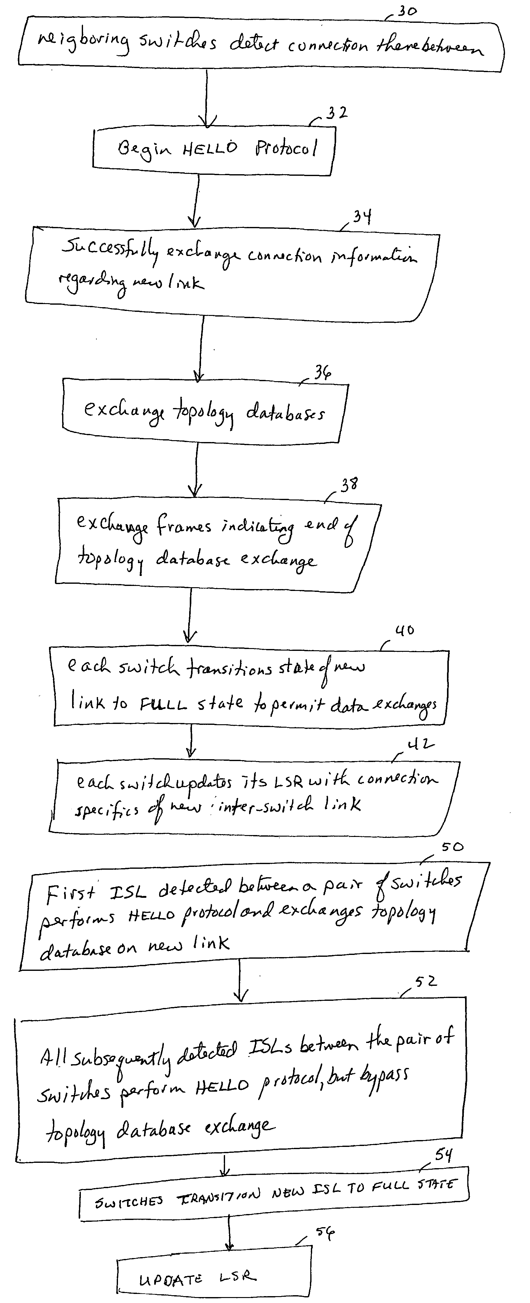
[0019] The preferred embodiments of the present invention solve the problems noted above by providing a network comprising a plurality of interconnected switches that implements an improved topology database synchronization technique. The technique involves each switch detecting a newly formed physical connection to a neighboring switch and only transmitting the switch's topology database to the neighboring switch if the database has not already been provided to the neighboring switch. When a new physical connection is detected over one of the local switch's ports to a neighboring switch, the local switch determines whether any of its other ports have already been connected to the same neighboring switch. If no other port on the local switch has been connected to the neighboring switch, the local switch transmits its topology database to the neighboring switch. If the local switch determines that, in fact, it has already been connected to the neighboring switch via another one of it...


PUM


Abstract

A network comprises a plurality of interconnected switches that implement a topology database synchronization technique in which each switch determines whether its topology database has already been transmitted to a neighboring switch when a new link is formed to the neighboring switch. When a new electrical connection is detected, the local switch determines whether any of its other ports have already been connected to the same neighboring switch. If no other port on the local switch has been connected to the neighboring switch, the local switch transmits its topology database to the neighboring switch. If the local switch determines that it has already been connected to the neighboring switch via another one of its ports, the local switch does not yet again copy of the database to the neighboring switch. Also, link state record updates are propagated via only one inter-switch link to a neighboring switch, not all possible links.

Description

[0001] Not applicable.[0002] Not applicable.[0003] 1. Field of the Invention[0004] The present invention generally relates to computer networks. More particularly, the invention relates to electronic switches through which communications pass from one point in a network to another. Still more particularly, the invention relates to an improved technique for synchronizing topology databases between switches in a network.[0005] 2. Background Information[0006] Initially, computers were most typically used in a standalone manner. It is now commonplace for computers and other types of computer-related and electronic devices to communicate with each other over a network. The ability for computers to communicate with one another has lead to the creation of networks ranging from small networks comprising two or three computers to vast networks comprising hundreds or even thousands of computers. Networks can be set up to provide a wide assortment of capabilities. For example, networks of comp...

Claims


Application Information

Patent Timeline
IPC IPC(8): H04L12/24
CPCH04L41/12
Inventor VALDEVIT, EZIOABRAHAM, VINEET
Owner AVAGO TECH INT SALES PTE LTD
Why Eureka
Try Eureka