Transferring between or within networks a telecommunication service to a user terminal

a telecommunication service and user terminal technology, applied in the field of telecommunications network services transfer, can solve the problems of large amount of network resources that are sometimes required to handle calls to some user terminals, affecting the service quality of users, and the level of network load, so as to improve the system capacity, reduce the amount of network resources, and improve the radio condition

Inactive Publication Date: 2006-06-22
LUCENT TECH INC
View PDF3 Cites 96 Cited by
  • Summary
  • Abstract
  • Description
  • Claims
  • Application Information

AI Technical Summary

Benefits of technology

[0009] The transfer of service to a user from one network to another network can occur when a user terminal, which is wireless, experiences better radio conditions in respect of that another network. In consequence, less network resources are required to provide the service to the user. As a result, the networks can provide services to more users at a time overall. In other words, system capacity is increased.

Problems solved by technology

Other factors are the current channel conditions to the user terminal, where the user terminal is wireless, and also network conditions, such as current interference levels and level of network loading.
Also, as the user terminal moves, the user terminal can experience varying levels of interference to signals received from the network.
This interference is due to nearby cells using channels of frequency bands that overlap.
In consequence of these variations, a large amount of network resources can sometimes be required to handle calls to some user terminals.
This can give rise to network congestion, possibly leading to calls being dropped.
In consequence, the negotiated charge rate for the service may no longer be proportionate to the radio resources expended by the network.
For example, a user terminal that is initially cheap to support in terms of network resources, can become expensive to support in terms of network resources, should it move to a location experiencing worse radio attenuation conditions.
This is frustrating to the network operator, particularly when the user terminal, as a result of the changing radio conditions, has a much better signal path to a network of a competing operator.
Such an approach has disadvantages.
There is a lack of transparency to the user as to which network is providing the service.
Furthermore, penalties for dropped calls, or poor quality of service, are not necessarily associated with the operator of the network that provides the service.

Method used


Image

  • Transferring between or within networks a telecommunication service to a user terminal
  • Transferring between or within networks a telecommunication service to a user terminal
  • Transferring between or within networks a telecommunication service to a user terminal

Examples


Embodiment Construction

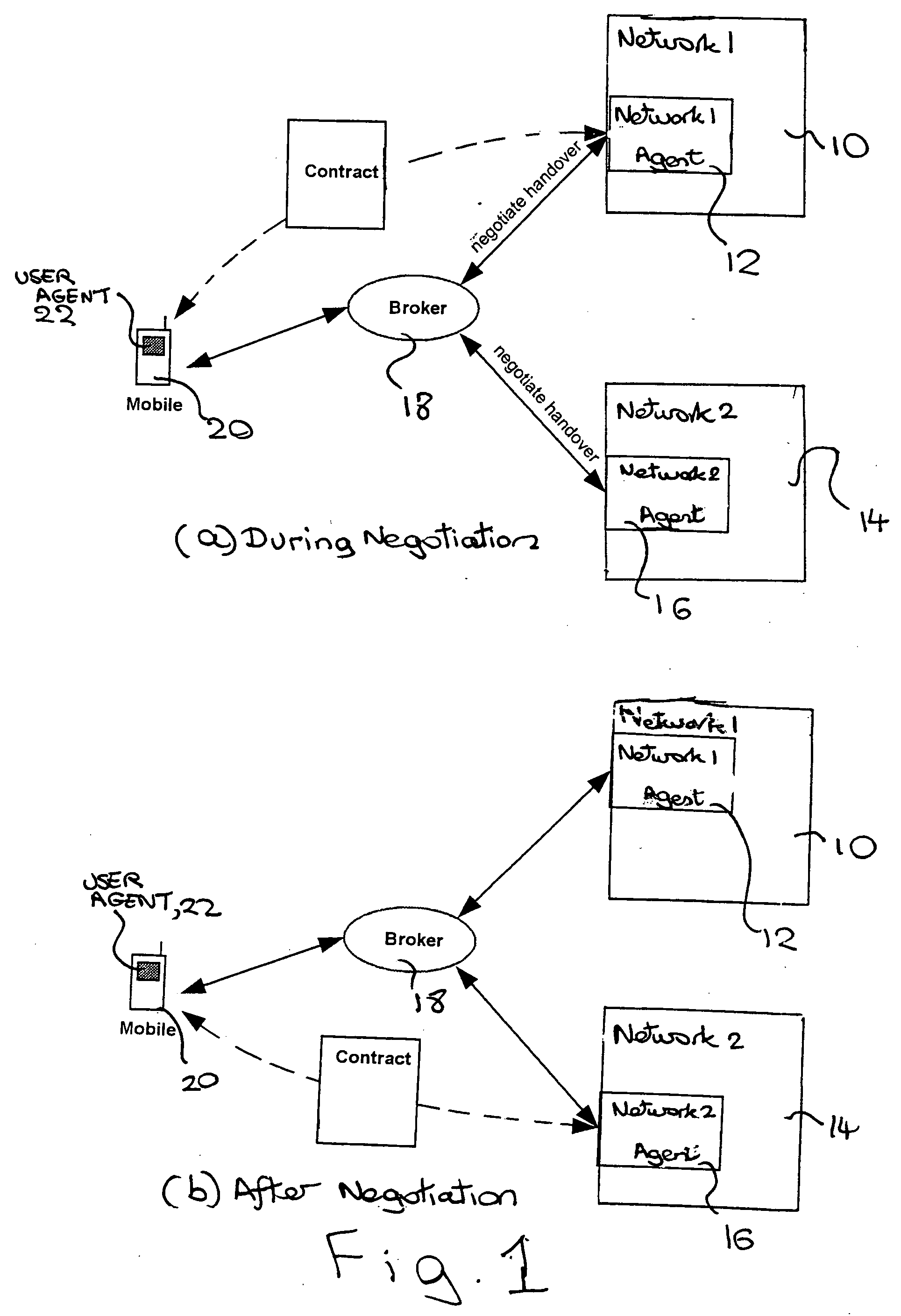
[0016] As shown in FIG. 1, a first radio access network (RAN) 10 includes a software entity that is a negotiation agent 12. A second radio access network 14 also includes a corresponding software entity of a negotiation agent 16. The networks 10,14 are radio access networks such as Global System for Mobiles (GSM), Universal Mobile Telecommunication Systems (UMTS) or Wireless Local Area Network (WLAN) networks. These networks can provide data, voice, video or other services. Each network 10,14 is under the control of a corresponding operator. The networks 10,14 overlap in their areas of coverage such that a user terminal at a location can connect to one of several networks.

[0017] Another software entity, which is also a negotiation agent, is provided, known as a broker 18. User terminals 20, which are mobile, are provided, one of which is shown in FIG. 1 for simplicity. Each mobile user terminal 20 includes within itself a software entity, which is a negotiation agent, known as a us...


PUM


Abstract

A method is provided of providing a service to a user terminal. According to this method, a first network agrees with the user terminal to provide the service at a certain charge rate, then starts to provide the service. Subsequently at least one other network is invited by the first network to provide the service. The first network receives at least one offer from the other networks to provide the service to the user terminal. The first network then accepts one of the offers, such that the one of said other networks thereafter provides the service and charges the user terminal without the first network being involved.

Description

FIELD OF THE INVENTION [0001] The present invention relates to the handling of services in telecommunications networks. DESCRIPTION OF THE RELATED ART [0002] Agent-based architectures have been suggested as a way of managing telecommunication systems, in particular wireless telecommunication systems. Agent-based architectures are a form of distributed computing where distributed autonomous software entities interact with each other. These software entities are referred to as negotiation agents, or simply, agents. [0003] In a telecommunications environment, an agent-based architecture allows the charge rate for a service requested by a user to be negotiated. The charge rate can depend on the nature of the service, for example video streaming or voice. Other factors are the current channel conditions to the user terminal, where the user terminal is wireless, and also network conditions, such as current interference levels and level of network loading. [0004] These other factors vary d...

Claims


Application Information

Patent Timeline
Patent Type & Authority Applications(United States)
IPC IPC(8): H04M11/00H04W28/16
CPCH04M15/00H04M15/8038H04M15/805H04M2215/0168H04M2215/34H04M2215/7442H04M2215/7457H04W28/16
Inventor CLAUSSEN, HOLGERHO, LESTER TSE WEEMULLANY, FRANCIS JOSEPHSAMUEL, LOUIS GWYN
Owner LUCENT TECH INC
Why Eureka
Try Eureka