Milk filtration and filter regeneration

a technology of filter regeneration and filtration, which is applied in the direction of filtration separation, milk treatment, separation process, etc., can solve the problems of complex filtration, still be solid contaminants, e.g. animal hairs and dirt, and leave at the teats,

Inactive Publication Date: 2004-02-19
DELAVAL HLDG AB
View PDF3 Cites 5 Cited by
  • Summary
  • Abstract
  • Description
  • Claims
  • Application Information

AI Technical Summary

Benefits of technology

0013] Still further objects of the invention are to provide a method for milk filtration and filter regeneration, which is effective and which can perform the regeneration automatically, and to provide a method of milking comprising said method for milk filtration and filter regeneration.

Problems solved by technology

Nevertheless, there may still be solid contaminants, such as e.g. animal hairs, and dirt, left at the teats, which can be drawn into the milk lines connected to the teatcups by the milking vacuum typically employed.
Milk filtration is, however, complicated as the milk contains emulsified fat, which appears as small spherical particles having a diameter of up to 10 microns.
If fat is prevented from passing through, the filter is rapidly clogged.
A drawback of such a filter, however, is that it has to be changed regularly since separated contaminants are settled partly within the filter layer.
Such demands for changes are difficult to fulfill in an automated milking system with a more or less continous milk flow.
Further, such changes are typically performed manually and they thus involve time consuming and costly work, sometimes also at very inconvenient times.

Method used


Image

  • Milk filtration and filter regeneration
  • Milk filtration and filter regeneration
  • Milk filtration and filter regeneration

Examples


Embodiment Construction

[0022] In the following description, for purposes of explanation and not limitation, specific details are set forth, such as particular techniques and applications in order to provide a thorough understanding of the present invention. However, it will be apparent to one skilled in the art that the present invention may be practiced in other embodiments that depart from these specific details. In other instances, detailed descriptions of well-known methods and apparatuses are omitted so as not to obscure the description of the present invention with unnecessary details.

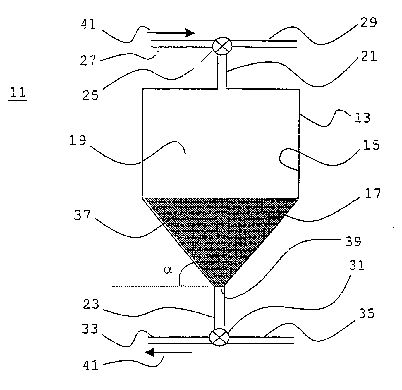
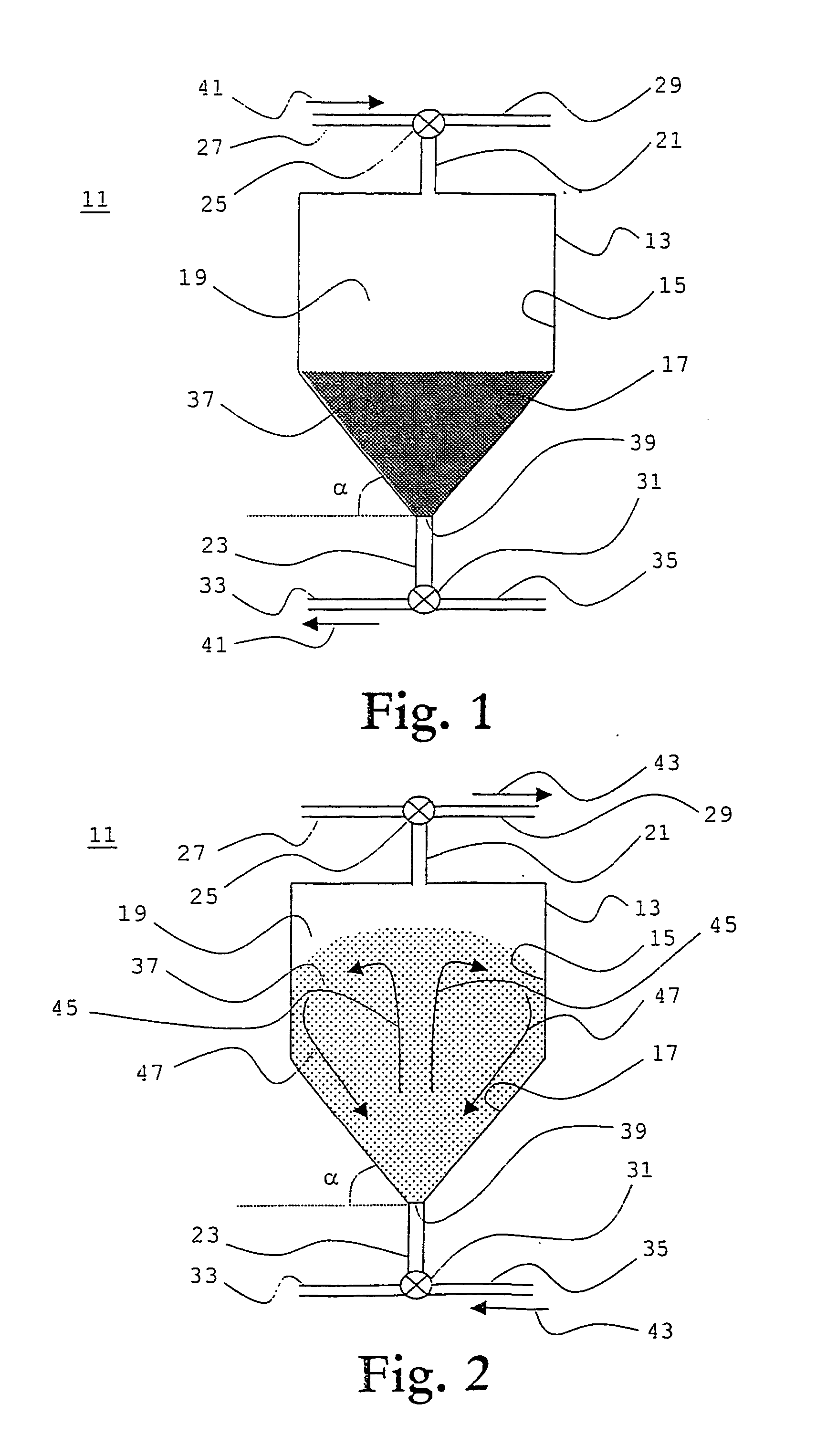
[0023] Referring to FIGS. 1 and 2, which show an apparatus 11 for milk filtration and filter regeneration, as being arranged in filtration mode and in regeneration mode, respectively, a preferred embodiment of the present invention will be described.

[0024] Apparatus 11 comprises a filter vessel 13 extending substantially vertically and including inner walls 15, 17 enclosing a filter vessel interior 19, a milk flow inle...


PUM

PropertyMeasurementUnit
diameteraaaaaaaaaa
angleaaaaaaaaaa
cylindrical symmetryaaaaaaaaaa

Abstract

The present invention refers to an apparatus (11) and a method for milk filtration and filter regeneration. The apparatus comprises a filter vessel (13); a loose filter material (37) housed within the vessel for filtering out contaminants in the milk; and a grid (31) arranged in front of the milk flow outlet to prevent the loose filter material from leaving the vessel. The vessel includes inner walls (15, 17); a milk inlet (21); a milk outlet (23); a cleaning fluid inlet (23) arranged substantially vertically at the lowermost portion of the vessel, through which a cleaning fluid jet can be injected, and a cleaning fluid outlet (21) arranged at the upper portion of the vessel. The lower portions (17) of the inner walls of the vessel form an angle (alpha) with respect to the horizontal plane, the angle being larger than the angle of repose for the filter material in the cleaning fluid. Thus, the filter material, which is flowed vertically upwards (45) by the cleaning fluid jet, moves substantially radially outwards (45) with respect to the jet to descend downwards (47) and slide back (47) towards the jet by aid of the angled inner wall portions.

Description

[0001] The present invention generally relates to dairy farm machine milking and to milk filtering related thereto.[0002] Particularly, the invention relates to apparatus and methods for milk filtration and filter regeneration, to automated milking machines and automated milking systems comprising such a milk filtration apparatus, and to methods of milking.DESCRIPTION OF RELATED ART AND BACKGROUND OF THE INVENTION[0003] When a milking animal, such as a cow, presents for milking it is important to ensure that the teatcups to be attached to the teats of the milking animal are clean and free of any condition that could contaminate the milk drawn from the milking animal. This need applies to both manual and automatic application of milking apparatus. Therefore, it is customary to wash the teatcups between the milking of each milking animal, either a cleaning liquid or only water is used.[0004] Nevertheless, there may still be solid contaminants, such as e.g. animal hairs, and dirt, left...

Claims


Application Information

Patent Timeline
Patent Type & Authority Applications(United States)
IPC IPC(8): A01J11/06B01D24/10
CPCA01J11/06B01D24/105B01D24/4684
Inventor BJORK, ANDERSLIDMAN, MAGNUS
Owner DELAVAL HLDG AB
Why Eureka
Try Eureka