
Discharge methodologies for lithium/silver vanadium oxide cells to manage voltage delay and permanent RDC growth region

a technology of lithium vanadium oxide and discharge voltage, applied in secondary cells, electrochemical generators, cell components, etc., can solve the problems of voltage delay, limiting effectiveness and even the proper functioning, and reducing discharge voltages

Inactive Publication Date: 2004-02-26
WILSON GREATBATCH LTD
View PDF16 Cites 2 Cited by
  • Summary
  • Abstract
  • Description
  • Claims
  • Application Information

AI Technical Summary

Benefits of technology

The present invention relates to an improved alkali metal electrochemical cell that can reduce voltage delay and Rdc growth during pulse discharging, especially at about (35% to 70%) of depth-of-discharge (DOD). The invention aims to address the undesirable characteristics of voltage delay and Rdc growth in such cells and to provide a solution for delivering the high capacity needed for powering implantable medical devices. The invention proposes a method for reforming the connected capacitors of the cell at least partially restoring and preserving their charging efficiency by subjecting them to novel discharge regimes. The technical effect of the invention is to minimize or eliminate voltage delay and Rdc growth in the about (35% to 70% DOD region, while maintaining the rated breakdown voltages of the cell's capacitors.

Problems solved by technology

Thus, decreased discharge voltages and the existence of voltage delay are undesirable characteristics of an alkali metal / silver vanadium oxide cell subjected to current pulse discharge conditions in terms of their influence on devices such as implantable medical devices including pacemakers and cardiac defibrillators.
Depressed discharge voltages and voltage delay are undesirable because they limit the effectiveness and even the proper functioning of both the cell and the associated electrically powered device under current pulse discharge conditions.

Method used


Image

  • Discharge methodologies for lithium/silver vanadium oxide cells to manage voltage delay and permanent RDC growth region
  • Discharge methodologies for lithium/silver vanadium oxide cells to manage voltage delay and permanent RDC growth region

Examples


Embodiment Construction

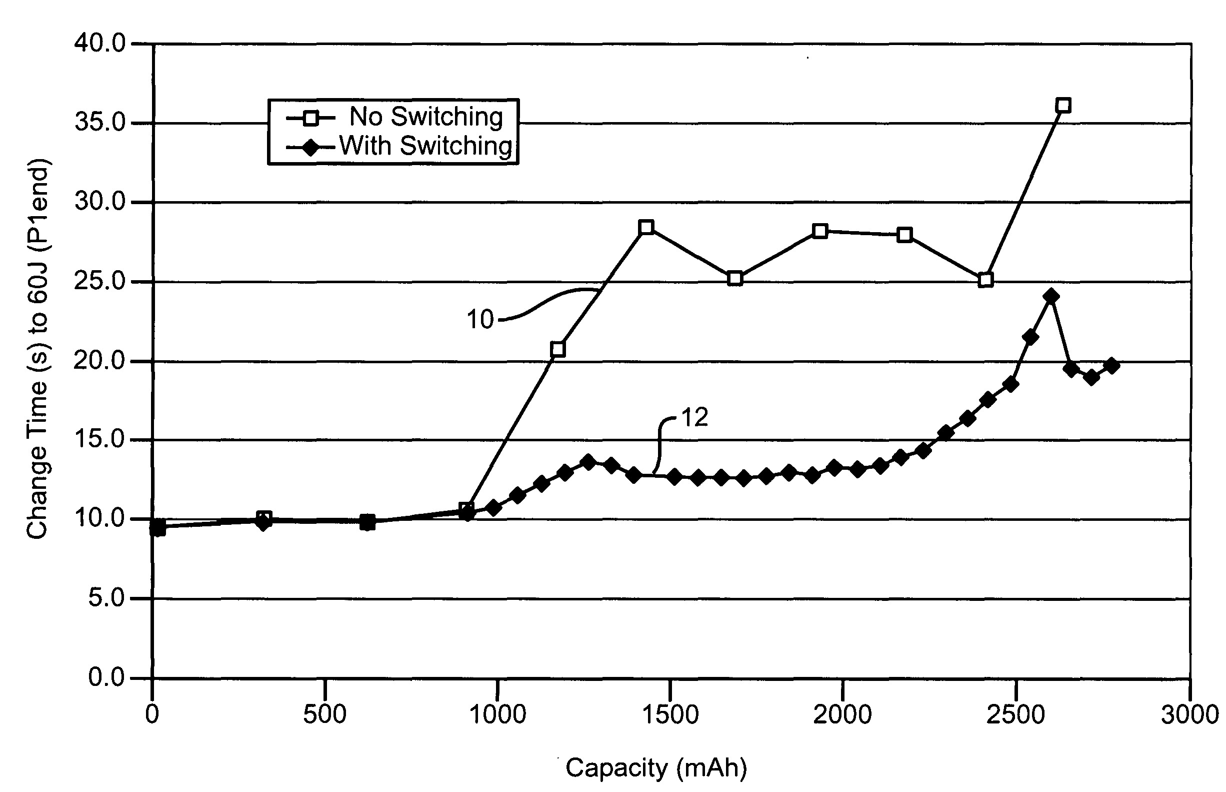
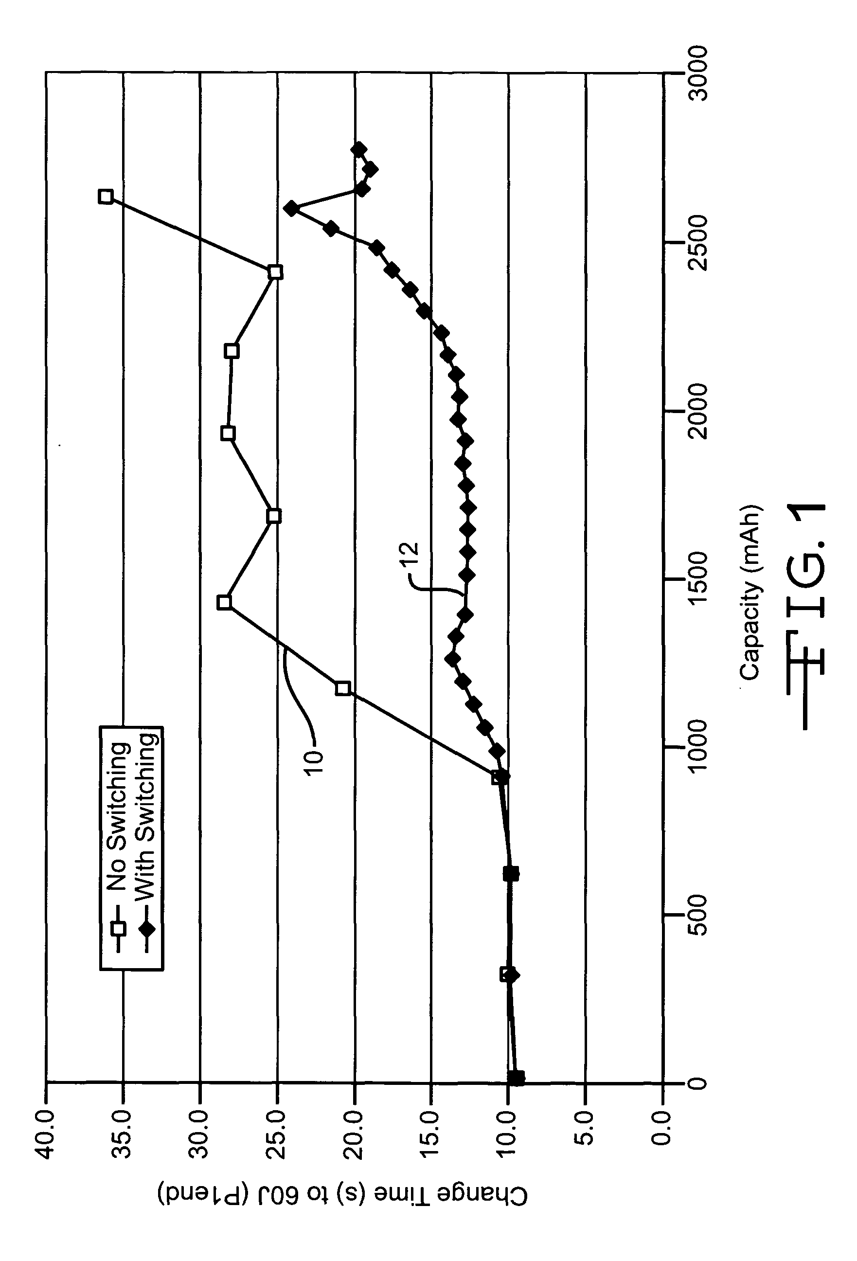
[0040] FIG. 1 is a graph drawn from the average discharge characterization results of two Li / SVO cell groups, each group having five cells of similar construction and energy density. The cells were periodically discharged at 50.degree. C. under a 16.5 k.OMEGA. load with superimposed pulse trains applied every 63 days. The pulse trains consisted of two 2.5 amps, 10-second pulses with 15 seconds rest between each pulse. This type of discharge is termed 24 month accelerated discharge data (24MADD), which simulates 60MADD at 37.degree. C. with pulse intervals of 154 days. The cells used to construct curve 10 were subjected to this protocol throughout the entire test. However, the cells used to construct curve 12 were switched to a more rapid discharge protocol after the fourth pulse train. Then, they were pulse discharged every 14 days until the end of the test.

[0041] It can be seen that in the case of the cells of curve 10, the charge time to 60 joules at pulse 1 end significantly incr...


PUM

PropertyMeasurementUnit
current densitiesaaaaaaaaaa
electrical currentaaaaaaaaaa

Abstract

It is known that reforming implantable defibrillator capacitors at least partially restores and preserves their charging efficiency. An industry-recognized standard is to reform implantable capacitors by pulse discharging the connected electrochemical cell about once every three months throughout the useful life of the medical device. A Li / SVO cell typically powers such devices. The present invention relates to methodologies for significantly minimizing, if not entirely eliminating, the occurrence of voltage delay and irreversible Rdc growth in the about 35% to 70% DOD region by subjecting Li / SVO cells to novel discharge regimes. At the same time, the connected capacitors in the cardiac defibrillator are reformed to maintain them at their rated breakdown voltages.

Description

[0001] This application claims priority based on provisional application Serial No. 60 / 405,173, filed Aug. 22, 2002.BACKGROUND OF INVENTION[0002] 1. Field of the Invention[0003] The present invention generally relates to the conversion of chemical energy to electrical energy. More particularly, this invention relates to an alkali metal electrochemical cell having reduced voltage delay and Rdc growth. A preferred couple is a lithium / silver vanadium oxide (Li / SVO) cell. In such cells, it is desirable to reduce voltage delay and permanent or irreversible Rdc growth at about 35% to 70% of depth-of-discharge (DOD) where these phenomena typically occur.[0004] 2. Prior Art[0005] Voltage delay is a phenomenon typically exhibited in a lithium / silver vanadium oxide cell that has been depleted of about 35% to 70% of its capacity and is subjected to high current pulse discharge applications. The voltage response of a cell that does not exhibit voltage delay during the application of a short dur...

Claims


Application Information

Patent Timeline
Patent Type & Authority Applications(United States)
IPC IPC(8): H01M4/40H01M4/48H01M4/485H01M4/54H01M4/58H01M10/0525H01M10/36H01M10/42H01M10/44H02J7/00
CPCH01M4/40H01M4/485H01M4/54H01M10/44H01M10/0525H01M10/4264H01M4/5825Y02E60/10
Inventor GAN, HONGWAITE, NOELLESYRACUSE, KENNETHTAKEUCHI, ESTHER S.
Owner WILSON GREATBATCH LTD
Learn More