Check patentability & draft patents in minutes with Patsnap Eureka AI!

High sensitivity fiber optic rotation sensor

a high-sensitivity, fiber optic technology, applied in the direction of optical radiation measurement, photometry using electric radiation detectors, instruments, etc., can solve the problems of increased transmission loss, cumbersome loading fixtures, and low sensitivity of prior art sensors, and achieve the effect of reducing the loss of microbending in the fiber

Inactive Publication Date: 2004-03-04
THE GOVERNMENT OF THE UNITED STATES OF AMERICA AS REPRESENTED BY THE SEC OF THE NAVY NAVAL RES LAB WASHINGTON
View PDF12 Cites 0 Cited by
  • Summary
  • Abstract
  • Description
  • Claims
  • Application Information

AI Technical Summary

Problems solved by technology

Increasing the curvature by moving the plates together increased transmission loss.
These prior art sensors have relatively low sensitivity and require cumbersome loading fixtures.
The resulting microbending losses in the fiber vary the attenuation of light energy between an optical source and an optical detector.
Rotation of the rotatable member causes a distortion of the at least one loop in the optical fiber and a change in the intensity of the light passing through the optical fiber.

Method used


Image

  • High sensitivity fiber optic rotation sensor
  • High sensitivity fiber optic rotation sensor

Examples


Embodiment Construction

)

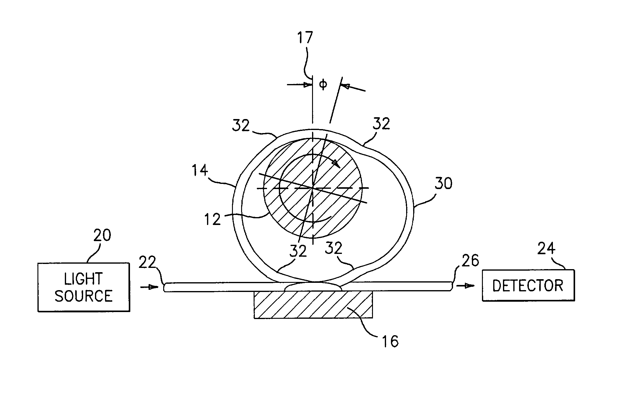
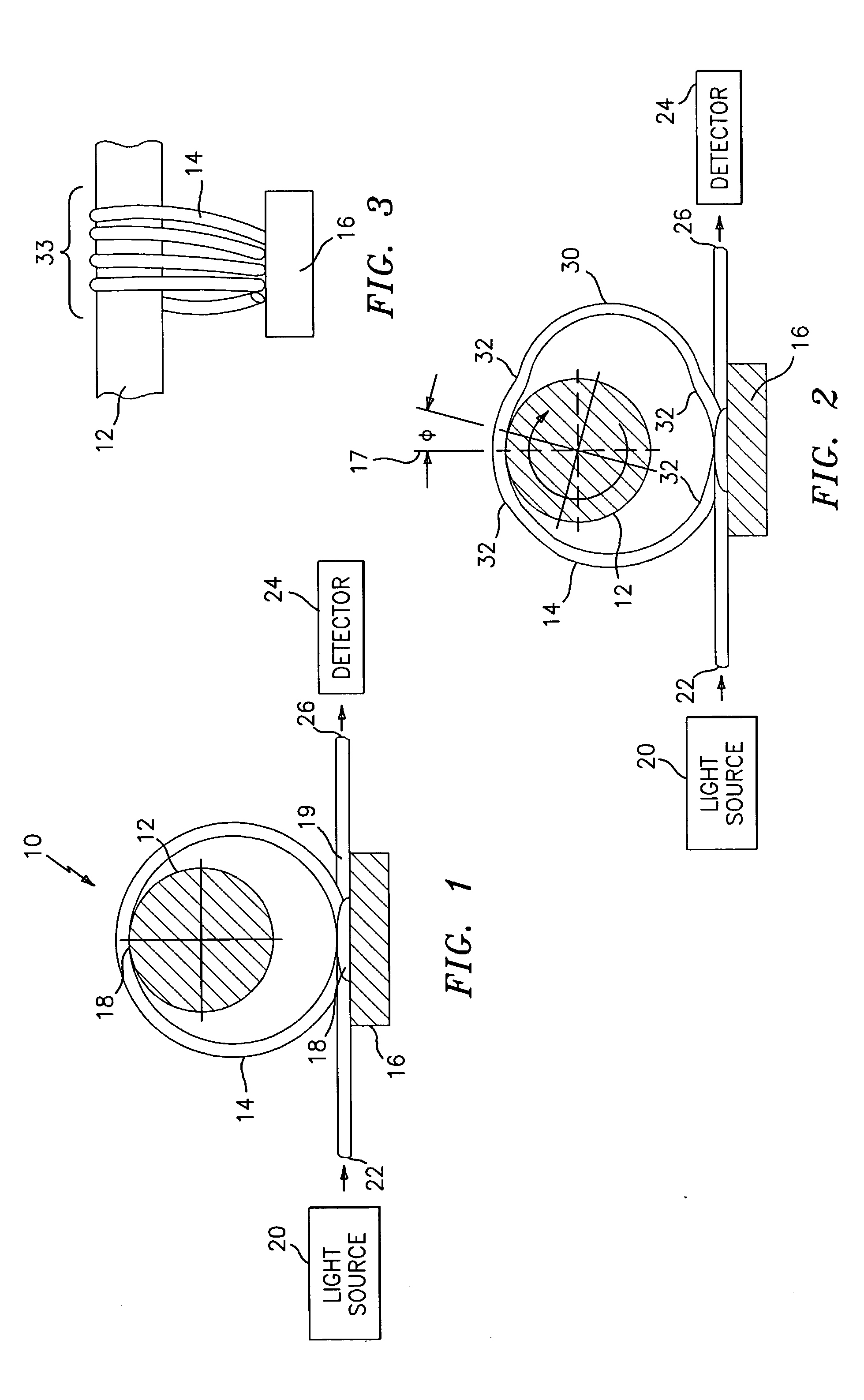
[0027] Referring now to FIG. 1, a sensor device 10 for detecting rotation of a member 12, such as an armature, is illustrated. The sensor device 10 includes at least one multimode optical fiber 14 configured in at least one loop around the rotatable member 12 which is supported on a stationary base 16. The optical fiber 14 is affixed to the stationary base 16 and to the rotatable member 12 along the lines 18. As can be seen from FIG. 1, the lines or affixation points 18 lie along an axis which is substantially perpendicular to a surface 19 of the base 16, and co-linear to the axis of rotation of member 12. While any suitable means known in the art may be used to affix the optical fiber 14 to the stationary base 16 and the rotatable member 12, it is preferred to bond the optical fiber 14 to the base 16 and the member 12 along the bond lines 18. Any suitable adhesive material known in the art may be used to effect these bonds.

[0028] The optical fiber 14 is connected to a light source...


PUM


Abstract

The present invention relates to a fiber optic rotation sensing device. The sensing device includes a stationary base, a rotatable member, and an optical fiber configured in at least one loop about the rotatable member. The optical fiber is secured to an exterior portion of the rotatable member and to the base. Rotation of the rotatable member causes a distortion of the at least one loop and a change in the intensity of the light passing through the optical fiber. The change in light intensity is measured to provide an indication of the degree of twist of the rotatable member.

Description

CROSS REFERENCE TO OTHER PATENT APPLICATIONS[0002] Not applicable.[0003] 1. Field of the Invention[0004] The present invention relates to a high sensitivity fiber optic rotation sensor.[0005] 2. Description of the Prior Art[0006] A microbend fiber optic sensor gives changes in the intensity of transmitted light in response to changes in fiber curvature. As curvature increases (bend radius decreases), a portion of the light traveling through the fiber is lost through dispersion and diffraction through the fiber wall. Fibers are used as sensors by measuring the change in transmitted light intensity. The physics of intensity based fiber optic sensors using microbends was first published by G. Zeidler, A. Hasselberg, and D. Schickentanz in their paper: "Effects of Mechanically Induced Periodic Bends on the Optical Loss of Glass Fibers", Optics Communications, Vol. 18, pp. 553-555, 1976. These investigators demonstrated the loss of intensity due to bending a fiber between a pair of plate...

Claims


Application Information

Patent Timeline
IPC IPC(8): G01L3/12G02B6/26
CPCG02B6/266G01L3/12
Inventor GAUTHIER, BENOIT G.SIENKIEWICZ, FRANK J.
Owner THE GOVERNMENT OF THE UNITED STATES OF AMERICA AS REPRESENTED BY THE SEC OF THE NAVY NAVAL RES LAB WASHINGTON
Features
  • R&D
  • Intellectual Property
  • Life Sciences
  • Materials
  • Tech Scout
  • Unparalleled Data Quality
  • Higher Quality Content
  • 60% Fewer Hallucinations
Learn More