Rocker arm

a technology of rocker arms and rocker arms, which is applied in the direction of mechanical control devices, process and machine control, instruments, etc., can solve the problems of reduced size and weight of rocker arms manufactured by press working techniques, undue reduction in productivity,

Inactive Publication Date: 2004-03-11
NTN CORP
View PDF4 Cites 44 Cited by
  • Summary
  • Abstract
  • Description
  • Claims
  • Application Information

AI Technical Summary

Problems solved by technology

Specifically, where the required flat outer surface region is to be secured on the connecting wall of the rocker arm manufactured by means of the press working technique, the arm width tends to increase as compared with that in the rocker arm manufactured by means of the precision casting technique, with the consequence that reduction in size and weight of the rocker arm manufactured by means of the press working technique is limited as compared with that manufactured by means of the precision casting technique.
Thus, this additional plastic deforming step taken after the press working step of producing the arm body of a generally inverted U-sectioned configuration would not result in an undue reduction in productivity.
If the radius of curvature of the outer chamfered corner is equal to or larger than the wall thickness of the arm body, a relatively large width of the flat outer surface area cannot be effectively secured on the connecting wall.
It is to be noted that since the arm body prepared from the plate material by the use of the press working technique has such a relatively small wall thickness as to allow it to be manufactured lightweight, a sufficient depth can hardly be obtained in the internally helically threaded hole for threadingly receiving the externally helically threaded pivot member or valve drive member.

Method used


Image

  • Rocker arm
  • Rocker arm
  • Rocker arm

Examples


first embodiment

[0059] The helical threads 12b each defined in that portion of the inner surface of each of the side walls 5 occupy a respective portion of a cylindrical extension of the internally helically threaded hole 12. Each thread 12b is made up of a plurality of screw teeth extending at the same helix as that of teeth of the internally helically threaded hole 12, so that when the adjustment screw 7 is inserted into the threaded hole 12, the externally helically threaded screw shank 7a of the adjustment screw 7 can be threadingly engaged with not only the teeth of the threaded hole 12, but also the teeth of the helical threads 12b in the side walls 5. Thus, the helical threads 12b so defined in the side walls 5 do in essence form respective part of the cylindrical extension of the internally helically threaded hole 12 in the connecting wall 6. Other structural features of the rocker arm 1 according to the embodiment of FIGS. 6A to 7B are similar to those shown in and described in connection ...

third embodiment

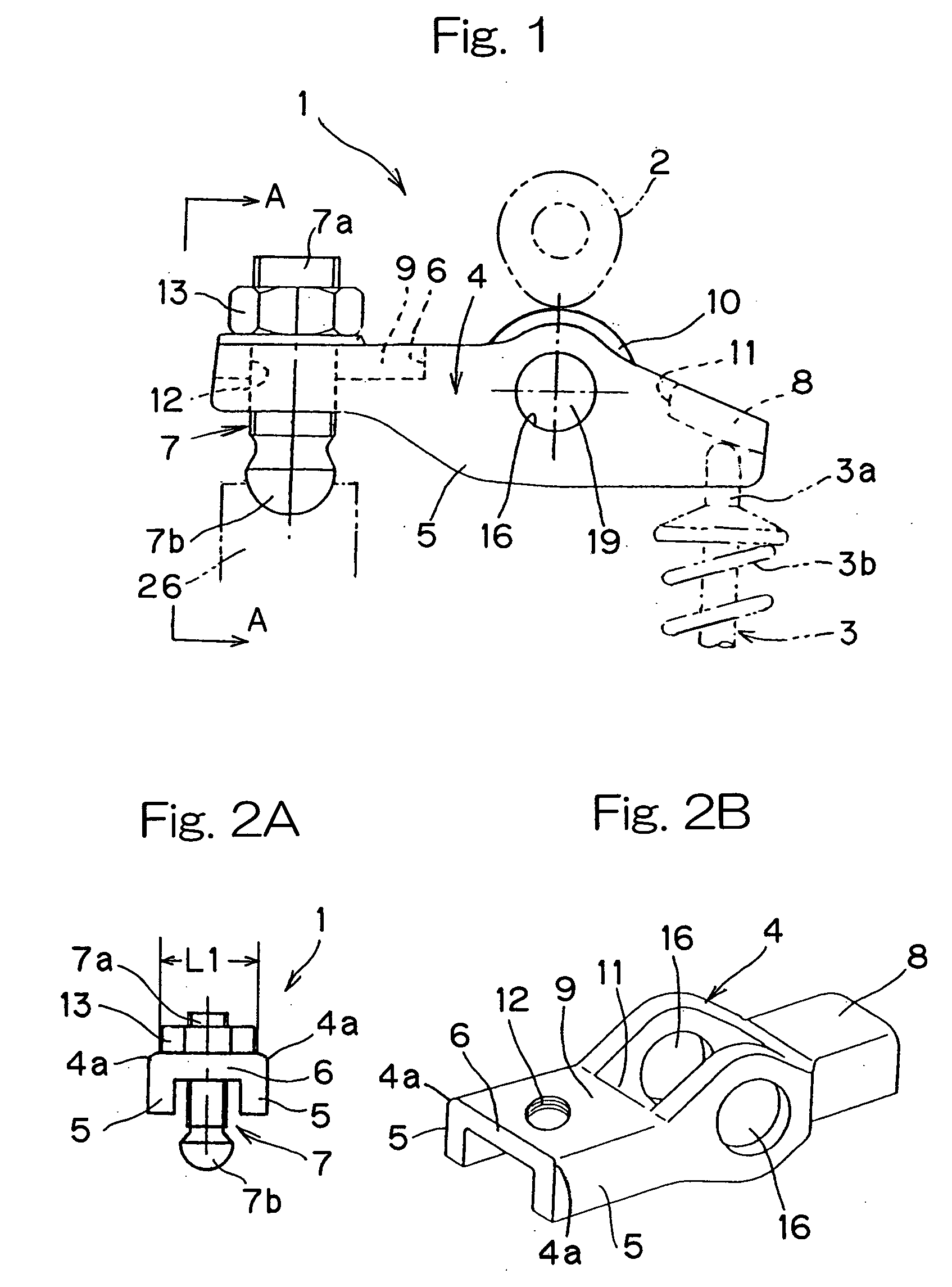
[0060] shown in and described with reference to FIGS. 6A to 7B, in which the helical threads 12b are formed in the side walls 5 as respective parts of the cylindrical extension of the threaded hole 12 in the connecting wall 6, the screw shank 7a of the adjustment screw 7 can be threadingly engaged with not only the teeth of the threaded hole 12, but also the teeth of the helical threads 12b in the side walls 5. Thus, those portions of the mutually confronting inner surfaces of the opposite side walls 5 can also be utilized as respective parts of the threaded hole 12. Accordingly, not only can a threading strength be secured, but also the width LI of the flat outer surface region of the arm body 4 can further be reduced, thereby facilitating reduction in size and weight of the rocker arm 1 as a whole.

[0061] FIGS. 8 to 9B illustrates a fourth preferred embodiment of the present invention is applied to the center pivot type in which the rocker arm is rockingly supported at a generally...


PUM

PropertyMeasurementUnit
thicknessaaaaaaaaaa
depthaaaaaaaaaa
depthaaaaaaaaaa

Abstract

There is provided a rocker arm of a kind in which even though the rocker arm is manufactured by the use of a press working technique the arm width can be minimized while the flat outer surface region of a required width is secured on an outer surface of the connecting wall, thereby contributing to reduction in size and weight of the rocker arm. This rocker arm 1 is capable of being driven by a cam 2 for selectively opening and closing a valve 3 of an internal combustion engine. This rocker arm 1 includes an arm body 4 prepared by bending a single plate material to represent a generally inverted U-shaped section including opposite side walls 5 and a connecting wall 6 bridging between the opposite side walls 5. A roller 10 engageable with the cam 2 is rotatably mounted on a portion of the arm body 4 generally intermediate of the length thereof. A valve drive element 8 is mounted on one end of the arm body 4 for driving the valve 4, while an end portion of the connecting wall 6 adjacent the other end of the arm body 4 is formed with an internally helically threaded hole 12 for threadingly receiving therein an externally helically threaded pivot member 7. An outer chamfered corner delimited between an outer surface of the connecting wall 6 and an outer surface of each of the opposite side walls and formed by bending is deformed to represent a plastically deformed portion 4a so formed by means of a plastic deformation technique that the outer chamfered corner represents a small radius of curvature R.

Description

[0001] 1. Field of the Invention[0002] The present invention relates to a rocker arm of a type adapted to be driven by a cam for selectively opening and closing a valve mounted on a cylinder head of the combustion engine.[0003] 2. Description of the Prior Art[0004] Inexpensive and lightweight rocker arms of this kind are currently manufactured by the use of, for example, a precision casting technique and a press working technique. Of those rocker arms, the rocker arms manufactured by the use of the press working technique to have a generally U-shaped section taken along the line perpendicular to the longitudinal sense thereof have now gained the mainstream in the market. The press-worked rocker arm has a screw-locked-pivot type and a contact-pivot type. The screw-locked-pivot type is illustrated in FIGS. 12A and 12B and is of a design in which a pivot area of a generally elongated arm body 34 is formed with an internally helically threaded hole 42 and a generally elongated pivot mem...

Claims


Application Information

Patent Timeline
Patent Type & Authority Applications(United States)
IPC IPC(8): B21D53/84F01L1/18F01L1/20
CPCB21K1/205F01L1/185F01L1/20F01L2101/00Y10T74/20882F01L2105/00Y10T29/49295Y10T74/2107F01L2103/00F01L2301/00F01L2303/00F01L2305/00
Inventor ABE, KATSUFUMI
Owner NTN CORP
Why Eureka
Try Eureka