Automated stereocampimeter and related method for improved measurement of the visual field

Active Publication Date: 2004-03-25
CENTFUSE TECH
View PDF5 Cites 77 Cited by
  • Summary
  • Abstract
  • Description
  • Claims
  • Application Information

AI Technical Summary

Benefits of technology

0020] Pursuant to another feature of the present invention, the more precise determining of the boundary includes selecting at least some of the additional points in dependence on the patient's responses to the testing of others of the additional points. Thus, the present methodology contemplates the selection of test points

Problems solved by technology

Pathological conditions in the retina result in areas of non-vision or reduced sensitivity of vision, or total loss of vision.
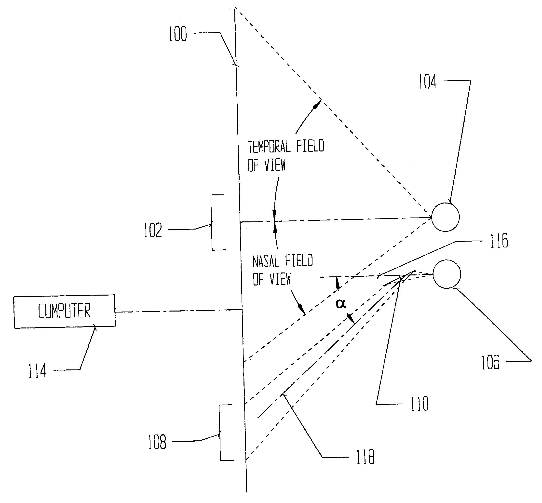
There is no apparatus routinely used that is designed for the study of the field of vision that is capable of rendering an accurate depiction of the visual field when a central scotoma exists, i.e. a pathological area of non-vision that includes the exact center of the field.
If the pathological area of non-vision, or scotoma, covers the center of the field, the patient is unable to see the central fixation point and therefore cannot fixate on it and the device produces incorrect results.
These devices, generically called visual field testers or automatic perimeters, are not adequate for testing any portion of the field of vision when a central scotoma exists in the exact center of the field.
However, commercially available visual field testing instruments fail to produce accurate results when the patient has a central scotoma.
The obvious problem is that when clinicians want to map such a field, they will ask the patient to stare at the central fixation target, which is impossible for these patients since that is exactly where they are blind.
This produces incorrect mapping of the entire field, and a central deficiency is reported as being located off-center when it is not, or can be missed altogether.
For patients with a large central scotoma, it is likely that it will be impossible for them to ever see this fixation light and shifting their gaze will not help.
A patient with large central scotoma (i.e. 40 degrees in extent) is not a candidate for a commercial visual field tester due to the fact that the patient cannot fixate.
Lack of fixation would give each data point on the resultin

Method used


Image

  • Automated stereocampimeter and related method for improved measurement of the visual field
  • Automated stereocampimeter and related method for improved measurement of the visual field
  • Automated stereocampimeter and related method for improved measurement of the visual field

Examples


Embodiment Construction

[0060] The invention will now be described in more detail by way of example with reference to the embodiments shown in the accompanying figures. It should be kept in mind that the following described embodiment in only presented by way of example and should not be construed as limiting the inventive concept to any particular physical configuration.

[0061] A preferred embodiment of the present invention is depicted cross section in FIG. 1A and three-dimensionally in FIG. 1B. A computer display 100 is used to present a patient with a graphical fixation area 102, and flashing test points 112 throughout the central visual field (for example 30 degrees nasally and 50 degrees temporally) to the eye under test 104. The technique described herein could certainly be extended to include the entire field of view of the eye as perimeters do, but will be described here only in the campimeter form. The computer display also serves to present to the eye not under test 106, a fixation area 108 that ...


PUM


Abstract

In a method for testing the visual field of a patient especially the central visual field, stereoscopic or binocularly displaced fixation images are presented under computer control to the respective eyes of the patient. In addition, a series of test images viewable by only one of the patient's eyes is generated under the control of the computer. The fixation images, one for each eye, are presented on two separate electronic displays, while the test images may be produced on a third display member different from the electronic displays. The computer is programmed to precisely determine a boundary between points corresponding to unseen test images and points corresponding to seen test images, by automatically testing additional points in a region located about the curve and between points corresponding to unseen test images and points corresponding to seen test images.

Description

CROSS-REFERENCE TO A RELATED APPLICATION[0001] This application relies for priority purposes on U.S. provisional application No. 60 / 412,434 filed Sep. 20, 2002.[0003] This invention relates to a method and an associated apparatus for measuring the visual field, especially the central visual field. The method and the apparatus of the present invention are particularly useful in mapping scotomas, especially central scotomas.[0004] Measurements of the visual field are considered very important in ophthalmology in clinical practice and are utilized for following diseases and treatments in glaucoma, diabetes, other vascular diseases, uveitis, retinal detachment, neurological disorders like brain tumors, etc. Visual field examinations test differential light sensitivities at various locations within the visual field of the eye in a subject being tested. The visual field is defined as that portion of space that is visible to the fixated eye.[0005] Perimetric and camperimetric tests are det...

Claims


Application Information

Patent Timeline
IPC IPC(8): A61B3/024
CPCA61B3/024
Inventor CAPPO, ANTHONY P.BENNETT, GREGORYORR, MATTHEW D.LUBKIN, VIRGINIA
Owner CENTFUSE TECH
Why Eureka
Try Eureka